
How to Use Power Bus: Examples, Pinouts, and Specs
 Design with Power Bus in Cirkit Designer
Introduction
A Power Bus is a conductive pathway designed to distribute electrical power efficiently to multiple components within a circuit. It serves as a centralized power distribution system, allowing various devices to share a common power source. Power buses are commonly used in prototyping, breadboarding, and PCB designs to simplify power management and reduce wiring complexity.
Explore Projects Built with Power Bus
 Open Project in Cirkit Designer
 Open Project in Cirkit Designer
 Open Project in Cirkit Designer
 Open Project in Cirkit Designer
Explore Projects Built with Power Bus
Open Project in Cirkit DesignerOpen Project in Cirkit DesignerOpen Project in Cirkit DesignerOpen Project in Cirkit DesignerCommon Applications and Use Cases
- Power distribution in breadboard circuits for prototyping
- Centralized power management in printed circuit boards (PCBs)
- Powering multiple sensors, actuators, or modules in embedded systems
- High-current power distribution in industrial and automotive systems
- Simplifying connections in LED arrays or lighting systems
Technical Specifications
Key Technical Details
- Voltage Rating: Typically supports up to 12V DC (varies by design)
- Current Rating: Ranges from 1A to 10A, depending on the bus material and size
- Material: Copper or tinned copper for high conductivity
- Form Factor: Available as PCB traces, busbars, or wire-based systems
- Insulation: Often includes a protective layer to prevent short circuits
Pin Configuration and Descriptions
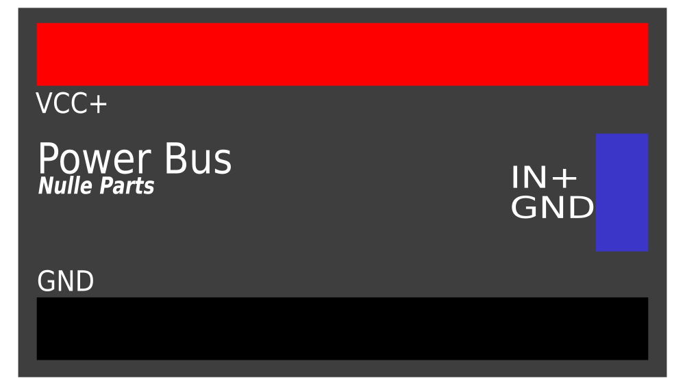
Power buses do not have traditional "pins" but are instead conductive pathways. However, in breadboard or PCB designs, they are often represented as rows or traces. Below is an example of how a power bus might be labeled in a breadboard or PCB context:
| Label | Description |
|---|---|
+ (Positive) |
Connects to the positive terminal of the power source (e.g., +5V, +12V). |
- (Negative) |
Connects to the negative terminal or ground (GND) of the power source. |
VCC |
Voltage Common Collector, often used as an alternative label for the positive bus. |
GND |
Ground connection, ensuring a common reference point for all components. |
Usage Instructions
How to Use the Power Bus in a Circuit
- Identify the Power Source: Determine the voltage and current requirements of your circuit and ensure the power bus can handle them.
- Connect the Power Source:
- Attach the positive terminal of the power source to the
+(positive) bus. - Attach the negative terminal of the power source to the
-(negative) bus.
- Attach the positive terminal of the power source to the
- Distribute Power:
- Use jumper wires or traces to connect individual components to the appropriate bus (e.g., sensors to
+and-). - Ensure all components share a common ground (
GND) to avoid potential differences.
- Use jumper wires or traces to connect individual components to the appropriate bus (e.g., sensors to
- Verify Connections:
- Double-check all connections to prevent short circuits or incorrect polarity.
- Use a multimeter to confirm voltage levels across the bus.
Important Considerations and Best Practices
- Current Capacity: Ensure the power bus can handle the total current draw of all connected components. Exceeding the current rating may cause overheating or damage.
- Voltage Drop: Minimize voltage drop by using short, thick traces or wires for high-current applications.
- Isolation: If multiple voltage levels are required, use separate power buses for each voltage to avoid interference.
- Polarity: Always verify the polarity of connections to prevent damage to components.
- Decoupling Capacitors: Place decoupling capacitors near sensitive components to stabilize the power supply and reduce noise.
Example: Using a Power Bus with an Arduino UNO
Below is an example of how to use a power bus to distribute power to multiple components connected to an Arduino UNO:
/* Example: Power Bus with Arduino UNO
   This code demonstrates powering multiple LEDs using a power bus.
   Ensure the power bus is connected to the Arduino's 5V and GND pins.
*/

const int led1 = 2; // Pin for LED 1
const int led2 = 3; // Pin for LED 2
const int led3 = 4; // Pin for LED 3

void setup() {
  pinMode(led1, OUTPUT); // Set LED 1 pin as output
  pinMode(led2, OUTPUT); // Set LED 2 pin as output
  pinMode(led3, OUTPUT); // Set LED 3 pin as output
}

void loop() {
  digitalWrite(led1, HIGH); // Turn on LED 1
  delay(500);               // Wait for 500ms
  digitalWrite(led1, LOW);  // Turn off LED 1

  digitalWrite(led2, HIGH); // Turn on LED 2
  delay(500);               // Wait for 500ms
  digitalWrite(led2, LOW);  // Turn off LED 2

  digitalWrite(led3, HIGH); // Turn on LED 3
  delay(500);               // Wait for 500ms
  digitalWrite(led3, LOW);  // Turn off LED 3
}
Troubleshooting and FAQs
Common Issues and Solutions
No Power on the Bus:
- Cause: Power source not connected or faulty.
- Solution: Verify the power source and ensure proper connections to the bus.
Overheating Wires or Traces:
- Cause: Exceeding the current rating of the power bus.
- Solution: Use thicker wires or wider PCB traces to handle higher currents.
Voltage Drop Across the Bus:
- Cause: Long or thin wires/traces causing resistance.
- Solution: Shorten the bus length or use lower-resistance materials.
Components Not Functioning Properly:
- Cause: Incorrect polarity or missing ground connection.
- Solution: Double-check all connections and ensure a common ground.
FAQs
Q: Can I use a single power bus for multiple voltage levels?
A: No, you should use separate buses for each voltage level to avoid interference and potential damage.Q: How do I protect the power bus from short circuits?
A: Use fuses or circuit breakers in series with the power source to prevent excessive current flow.Q: What materials are best for a high-current power bus?
A: Copper or tinned copper is ideal due to its high conductivity and low resistance.Q: Can I use a power bus for AC power distribution?
A: Power buses are typically designed for DC circuits. For AC applications, ensure the bus is rated for the voltage and frequency.
By following these guidelines, you can effectively use a power bus to simplify and enhance your circuit designs.