
How to Use ATMEGA32U4: Examples, Pinouts, and Specs
 Design with ATMEGA32U4 in Cirkit Designer
Introduction
The ATmega32U4 is a high-performance, low-power 8-bit microcontroller from Microchip's AVR family. It features 32KB of flash memory, 2.5KB of SRAM, and 1KB of EEPROM. One of its standout features is its built-in USB support, which eliminates the need for an external USB-to-serial converter, making it ideal for USB-enabled devices and embedded applications.
Explore Projects Built with ATMEGA32U4
 Open Project in Cirkit Designer
 Open Project in Cirkit Designer
 Open Project in Cirkit Designer
 Open Project in Cirkit Designer
Explore Projects Built with ATMEGA32U4
Open Project in Cirkit DesignerOpen Project in Cirkit DesignerOpen Project in Cirkit DesignerOpen Project in Cirkit DesignerCommon Applications
- USB keyboards, mice, and game controllers
- Data logging and USB communication devices
- Embedded systems requiring USB connectivity
- Prototyping with Arduino-compatible boards (e.g., Arduino Leonardo)
Technical Specifications
The following table outlines the key technical details of the ATmega32U4:
| Parameter | Value |
|---|---|
| Architecture | 8-bit AVR RISC |
| Operating Voltage | 2.7V - 5.5V |
| Flash Memory | 32KB |
| SRAM | 2.5KB |
| EEPROM | 1KB |
| Clock Speed | Up to 16 MHz |
| USB Support | Full-speed USB 2.0 |
| GPIO Pins | 26 |
| ADC Channels | 12 (10-bit resolution) |
| PWM Channels | 7 |
| Communication Interfaces | USB, UART, SPI, I2C (TWI) |
| Timers | 4 (Three 8-bit, One 16-bit) |
| Package | TQFP-44, QFN-44 |
Pin Configuration
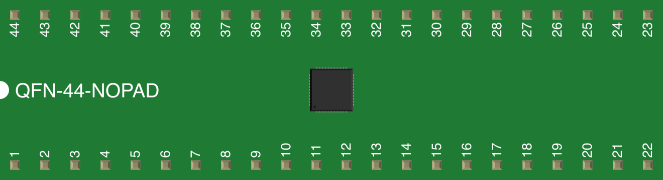
The ATmega32U4 has 44 pins, with the following key pin functions:
| Pin | Name | Description |
|---|---|---|
| 1 | VCC | Power supply (2.7V - 5.5V) |
| 2 | GND | Ground |
| 3 | RESET | Active-low reset input |
| 4 | XTAL1 | External clock/crystal input |
| 5 | XTAL2 | External clock/crystal output |
| 6-13 | PORTB[0:7] | General-purpose I/O, SPI interface |
| 14-21 | PORTC[6:7], PORTD[0:5] | General-purpose I/O, ADC, PWM, UART |
| 22-29 | PORTD[6:7], PORTE[0:5] | General-purpose I/O, USB D+, D- |
| 30-37 | PORTF[0:7] | General-purpose I/O, ADC inputs |
| 38-44 | PORTA[0:6] | General-purpose I/O, ADC inputs |
For a complete pinout diagram, refer to the ATmega32U4 datasheet.
Usage Instructions
Using the ATmega32U4 in a Circuit
- Power Supply: Connect the VCC pin to a regulated power source (2.7V - 5.5V) and GND to ground.
- Clock Configuration: Use an external crystal oscillator (e.g., 16 MHz) connected to XTAL1 and XTAL2, or configure the internal oscillator.
- USB Connectivity: Connect the USB D+ and D- pins to a USB port for communication or power.
- Programming: Use an ISP (In-System Programmer) or a USB bootloader to upload firmware.
- GPIO Usage: Configure pins as input or output in your firmware. Use pull-up resistors for input pins if needed.
Important Considerations
- USB Pull-Up Resistor: The ATmega32U4 has an internal USB pull-up resistor, so no external resistor is required.
- Decoupling Capacitors: Place 0.1 µF decoupling capacitors near the VCC and GND pins to reduce noise.
- Reset Circuit: Use a 10 kΩ pull-up resistor on the RESET pin for reliable operation.
- Clock Source: For USB applications, ensure the clock frequency is 16 MHz or 8 MHz.
Example: Using ATmega32U4 with Arduino UNO
The ATmega32U4 is commonly used in Arduino-compatible boards like the Arduino Leonardo. Below is an example of how to blink an LED connected to pin 13:
// Blink an LED connected to pin 13 on the ATmega32U4
void setup() {
  pinMode(13, OUTPUT); // Set pin 13 as an output
}

void loop() {
  digitalWrite(13, HIGH); // Turn the LED on
  delay(1000);            // Wait for 1 second
  digitalWrite(13, LOW);  // Turn the LED off
  delay(1000);            // Wait for 1 second
}
Troubleshooting and FAQs
Common Issues
USB Not Recognized:
- Ensure the USB D+ and D- lines are correctly connected.
- Verify that the clock source is configured for USB operation (e.g., 16 MHz crystal).
- Check for proper firmware with USB support.
Microcontroller Not Responding:
- Verify the power supply voltage (2.7V - 5.5V).
- Check the RESET pin configuration (10 kΩ pull-up resistor).
- Ensure the ISP or bootloader is functioning correctly.
Incorrect GPIO Behavior:
- Confirm the pin mode (input/output) is correctly set in the firmware.
- Check for external pull-up or pull-down resistors if required.
FAQs
Q: Can the ATmega32U4 be programmed using the Arduino IDE?
A: Yes, the ATmega32U4 is supported by the Arduino IDE. Select a compatible board like the Arduino Leonardo in the IDE.
Q: Does the ATmega32U4 support I2C communication?
A: Yes, the ATmega32U4 has a TWI (I2C) interface for communication with other devices.
Q: What is the maximum current per GPIO pin?
A: Each GPIO pin can source or sink up to 40 mA, but it is recommended to limit the current to 20 mA for safe operation.
Q: Can I use the internal oscillator for USB applications?
A: No, USB applications require a precise clock source, such as a 16 MHz external crystal.
For further details, refer to the official ATmega32U4 datasheet provided by Microchip.