How to Use GPS Antenna: Examples, Pinouts, and Specs
Introduction
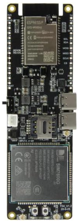
The LILYGO T-SIM7600G-H 4G LTE Module is a versatile GPS antenna designed to receive signals from GPS satellites, enabling precise location determination. This component is widely used in various applications, including navigation systems, asset tracking, and IoT devices. Its integration with the 4G LTE module allows for enhanced connectivity and data transmission capabilities.
Explore Projects Built with GPS Antenna


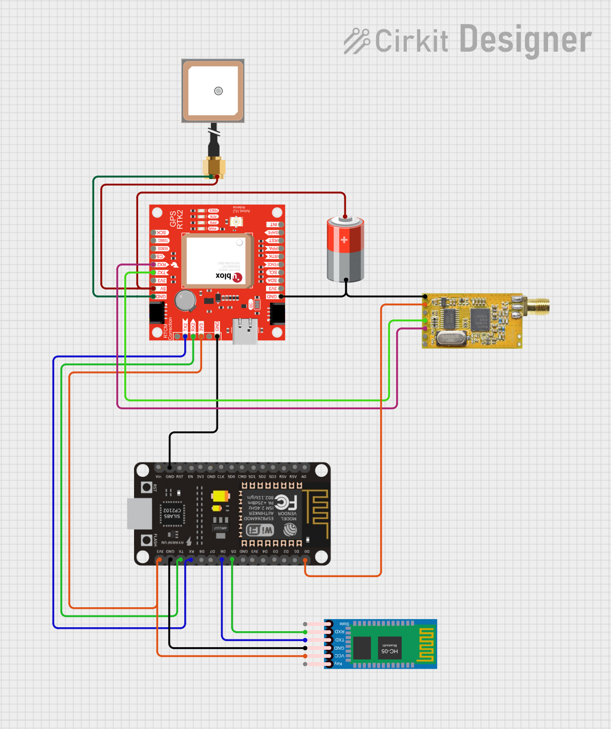
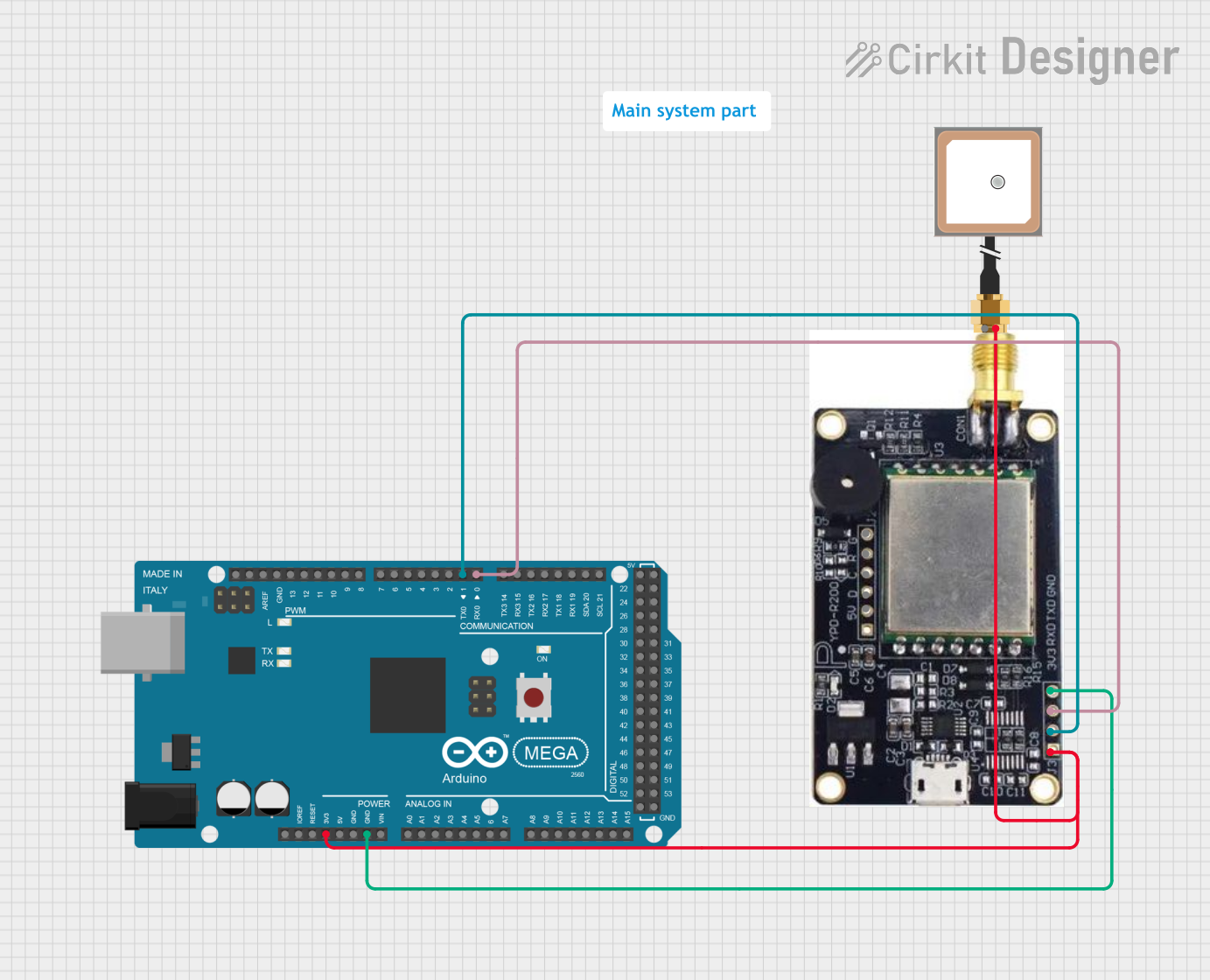
Explore Projects Built with GPS Antenna
Technical Specifications
Key Technical Details
| Parameter | Value |
|---|---|
| Manufacturer | LILYGO |
| Part ID | T-SIM7600G-H |
| Frequency Range | 1575.42 MHz (L1 band) |
| Voltage | 3.3V - 5V |
| Current Consumption | 20mA (typical) |
| Gain | 28 dB |
| Impedance | 50 Ohms |
| Connector Type | U.FL |
| Operating Temperature | -40°C to +85°C |
Pin Configuration and Descriptions
| Pin Number | Pin Name | Description |
|---|---|---|
| 1 | VCC | Power supply (3.3V - 5V) |
| 2 | GND | Ground |
| 3 | TX | Transmit data (to microcontroller) |
| 4 | RX | Receive data (from microcontroller) |
| 5 | PPS | Pulse per second (timing signal) |
| 6 | GND | Ground |
Usage Instructions
How to Use the Component in a Circuit
- Power Supply: Connect the VCC pin to a 3.3V or 5V power supply. Ensure that the power supply is stable and within the specified voltage range.
- Ground Connection: Connect the GND pins to the ground of your circuit to complete the electrical circuit.
- Data Communication: Connect the TX pin of the GPS antenna to the RX pin of your microcontroller (e.g., Arduino UNO) and the RX pin of the GPS antenna to the TX pin of your microcontroller.
- PPS Signal: The PPS pin provides a precise timing signal that can be used for synchronization purposes. Connect it to an appropriate input pin on your microcontroller if needed.
Important Considerations and Best Practices
- Antenna Placement: For optimal performance, place the GPS antenna in an open area with a clear view of the sky to ensure it can receive signals from multiple satellites.
- Power Supply: Use a stable power supply to avoid fluctuations that could affect the performance of the GPS antenna.
- Signal Interference: Keep the GPS antenna away from sources of electromagnetic interference, such as high-power transmitters or other electronic devices.
Example Code for Arduino UNO
#include <SoftwareSerial.h>

// Create a software serial port on pins 10 (RX) and 11 (TX)
SoftwareSerial gpsSerial(10, 11);

void setup() {
  // Start the hardware serial port for communication with the PC
  Serial.begin(9600);
  // Start the software serial port for communication with the GPS module
  gpsSerial.begin(9600);
}

void loop() {
  // Check if data is available from the GPS module
  if (gpsSerial.available()) {
    // Read a byte from the GPS module
    char c = gpsSerial.read();
    // Print the byte to the hardware serial port
    Serial.print(c);
  }
}
Troubleshooting and FAQs
Common Issues Users Might Face
No GPS Signal: The GPS antenna is not receiving any signals from satellites.
- Solution: Ensure the antenna has a clear view of the sky and is not obstructed by buildings or other structures. Check the connections and power supply.
Intermittent Signal: The GPS signal is weak or intermittent.
- Solution: Verify that the antenna is placed in an optimal location. Check for sources of interference and ensure the power supply is stable.
No Data Output: The GPS antenna is not transmitting data to the microcontroller.
- Solution: Check the TX and RX connections between the GPS antenna and the microcontroller. Ensure the baud rate settings match between the GPS module and the microcontroller.
Solutions and Tips for Troubleshooting
- Check Connections: Ensure all connections are secure and correctly oriented.
- Verify Power Supply: Use a multimeter to check the voltage at the VCC pin to ensure it is within the specified range.
- Use Diagnostic Tools: Utilize serial monitors and diagnostic software to check the data output from the GPS antenna.
By following this documentation, users can effectively integrate and utilize the LILYGO T-SIM7600G-H 4G LTE Module in their projects, ensuring reliable and accurate GPS functionality.