How to Use Piezo Electric Plat: Examples, Pinouts, and Specs
Introduction
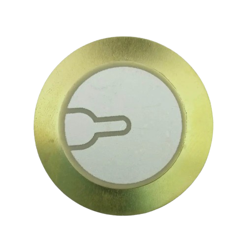
The Piezo Electric Plate (FSH2025), manufactured by Future Science Hub, is a versatile electronic component that generates an electric charge when subjected to mechanical stress. This property makes it ideal for applications such as vibration sensors, ultrasonic transducers, actuators, and energy harvesting systems. Its compact design and high sensitivity allow it to be integrated into a wide range of devices, from consumer electronics to industrial equipment.
Explore Projects Built with Piezo Electric Plat
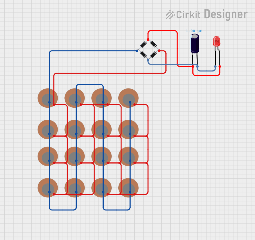
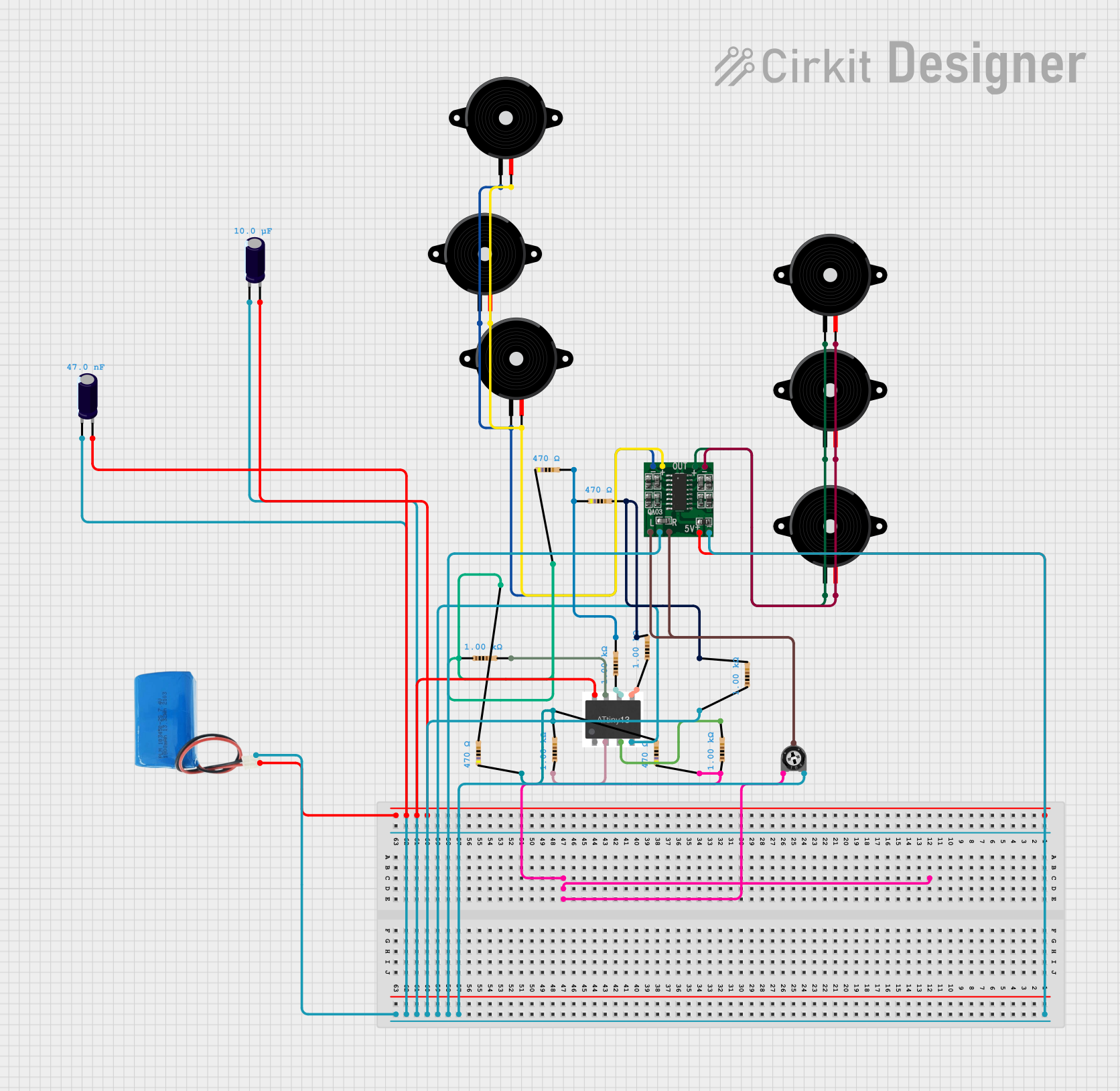
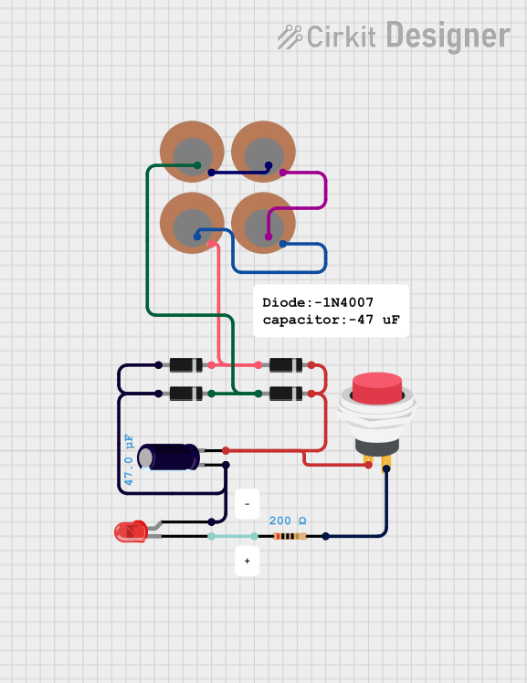
Explore Projects Built with Piezo Electric Plat
Common Applications
- Sensors: Detecting vibrations, pressure, or sound waves.
- Actuators: Producing mechanical motion in response to electrical signals.
- Energy Harvesting: Converting mechanical energy (e.g., vibrations) into electrical energy.
- Ultrasonic Devices: Used in medical imaging, cleaning systems, and distance measurement.
Technical Specifications
The following table outlines the key technical details of the FSH2025 Piezo Electric Plate:
| Parameter | Value |
|---|---|
| Manufacturer | Future Science Hub |
| Part ID | FSH2025 |
| Material | Lead Zirconate Titanate (PZT) |
| Dimensions | 20 mm x 25 mm x 0.5 mm |
| Operating Voltage Range | 0 - 30 V |
| Resonant Frequency | 6 kHz |
| Capacitance | 10 nF ± 10% |
| Maximum Output Voltage | 50 V (peak-to-peak) |
| Operating Temperature | -20°C to 80°C |
| Weight | 2 grams |
Pin Configuration and Descriptions
The FSH2025 Piezo Electric Plate has two terminals for electrical connections:
| Terminal | Description |
|---|---|
| Positive (+) | Connects to the positive side of the circuit. |
| Negative (-) | Connects to the ground or negative side of the circuit. |
Usage Instructions
How to Use the Component in a Circuit
Connecting the Piezo Plate:
- Identify the positive (+) and negative (-) terminals of the plate.
- Connect the positive terminal to the input of your circuit (e.g., an amplifier or microcontroller).
- Connect the negative terminal to the ground of your circuit.
Using as a Sensor:
- When used as a vibration or pressure sensor, the piezo plate generates a small voltage in response to mechanical stress.
- Use an operational amplifier (op-amp) to amplify the signal for further processing.
Using as an Actuator:
- Apply an AC voltage to the terminals to cause the plate to vibrate at its resonant frequency.
- Ensure the applied voltage does not exceed the maximum operating voltage (30 V).
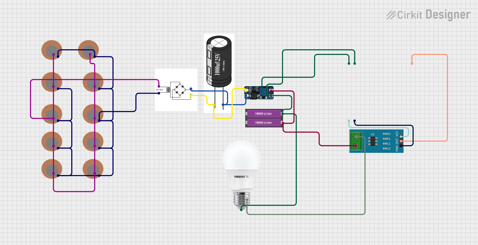
Energy Harvesting:
- Place the piezo plate in a location where it can experience consistent mechanical stress (e.g., under a vibrating surface).
- Use a rectifier circuit to convert the AC output to DC for charging a capacitor or battery.
Important Considerations and Best Practices
- Voltage Limits: Do not exceed the maximum operating voltage of 30 V to avoid damaging the plate.
- Mechanical Stress: Avoid applying excessive force, as this may crack or damage the plate.
- Mounting: Use non-conductive adhesive or mounting brackets to secure the plate without shorting the terminals.
- Signal Conditioning: For accurate measurements, use a low-noise amplifier and filter to process the output signal.
Example: Connecting to an Arduino UNO
The following example demonstrates how to use the FSH2025 Piezo Electric Plate as a vibration sensor with an Arduino UNO:
// Piezo Electric Plate (FSH2025) Vibration Sensor Example
// Connect the positive terminal of the piezo plate to A0 on the Arduino
// Connect the negative terminal to GND

const int piezoPin = A0;  // Analog pin connected to the piezo plate
int sensorValue = 0;      // Variable to store the sensor reading

void setup() {
  Serial.begin(9600);  // Initialize serial communication at 9600 baud
}

void loop() {
  sensorValue = analogRead(piezoPin);  // Read the voltage from the piezo plate
  Serial.print("Piezo Voltage: ");
  Serial.println(sensorValue);  // Print the sensor value to the Serial Monitor
  delay(100);  // Delay for 100 ms before the next reading
}
Troubleshooting and FAQs
Common Issues and Solutions
No Output Voltage:
- Cause: Loose or incorrect connections.
- Solution: Ensure the positive and negative terminals are securely connected to the circuit.
Weak Signal:
- Cause: Insufficient mechanical stress or poor signal conditioning.
- Solution: Apply more consistent stress or use an amplifier to boost the signal.
Component Damage:
- Cause: Exceeding the voltage or mechanical stress limits.
- Solution: Operate within the specified voltage and stress limits.
Noise in Output Signal:
- Cause: Electrical interference or poor grounding.
- Solution: Use shielded cables and ensure proper grounding in the circuit.
FAQs
Q1: Can the FSH2025 Piezo Electric Plate be used underwater?
A1: No, the FSH2025 is not waterproof. For underwater applications, use a waterproof piezoelectric sensor.
Q2: What is the lifespan of the FSH2025 Piezo Electric Plate?
A2: The lifespan depends on the operating conditions. Under normal use, it can last for several years.
Q3: Can I use the FSH2025 to generate power for a small device?
A3: Yes, but the output power is limited. It is suitable for low-power applications like charging small capacitors or powering low-energy sensors.
Q4: How do I clean the piezo plate?
A4: Use a soft, dry cloth to clean the surface. Avoid using water or solvents that may damage the material.
This concludes the documentation for the FSH2025 Piezo Electric Plate. For further assistance, refer to the manufacturer's datasheet or contact Future Science Hub.