How to Use AD8232: Examples, Pinouts, and Specs
Introduction
The AD8232 is an integrated signal conditioning module designed for biopotential measurements, such as ECG (electrocardiogram) signals. It amplifies and filters the small electrical signals generated by the heart, providing a clean output suitable for further processing or analysis. This compact and efficient module is ideal for wearable health devices, fitness monitoring systems, and medical instrumentation.
Explore Projects Built with AD8232
Explore Projects Built with AD8232
Common Applications and Use Cases
- ECG signal acquisition and monitoring
- Wearable health and fitness devices
- Heart rate monitoring systems
- Portable medical devices
- Biomedical research and development
Technical Specifications
Key Technical Details
- Supply Voltage: 2.0 V to 3.5 V
- Supply Current: 170 µA (typical)
- Input Voltage Range: 0 V to Vcc
- Output Voltage Range: 0 V to Vcc
- Gain: Programmable via external resistors
- Bandwidth: Configurable for ECG signals (0.5 Hz to 40 Hz typical)
- Operating Temperature Range: -40°C to +85°C
- Package: 20-lead LFCSP (4 mm × 4 mm)
Pin Configuration and Descriptions
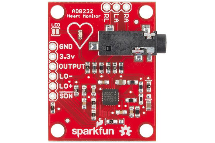
The AD8232 module typically comes with a breakout board for easier integration. Below is the pin configuration for the breakout board:
| Pin Name | Description |
|---|---|
| GND | Ground connection |
| 3.3V | Power supply input (3.3 V recommended) |
| OUTPUT | Analog output signal (filtered and amplified ECG signal) |
| LO+ | Leads-off detection positive input |
| LO- | Leads-off detection negative input |
| SDN | Shutdown pin (active low, used to enable/disable the module) |
| RA (Right Arm) | Input for the right arm electrode |
| LA (Left Arm) | Input for the left arm electrode |
| RL (Right Leg) | Input for the right leg electrode (used as reference or ground for the body) |
Usage Instructions
How to Use the AD8232 in a Circuit
- Power Supply: Connect the 3.3V pin to a regulated 3.3V power source and the GND pin to ground.
- Electrode Connections: Attach the RA, LA, and RL pins to the corresponding electrodes placed on the body. Ensure proper placement for accurate ECG signal acquisition:
- RA: Right arm
- LA: Left arm
- RL: Right leg (reference electrode)
- Output Signal: The OUTPUT pin provides the amplified and filtered ECG signal. Connect this pin to an analog input of a microcontroller or an oscilloscope for further processing or visualization.
- Leads-Off Detection: Use the LO+ and LO- pins to monitor if the electrodes are properly attached. These pins output a logic signal indicating the connection status.
- Shutdown Control: Use the SDN pin to enable or disable the module. Pull this pin low to activate the module.
Important Considerations and Best Practices
- Electrode Placement: Ensure the electrodes are securely attached to the skin and free from interference (e.g., sweat or movement artifacts).
- Power Supply: Use a clean and stable power source to avoid noise in the ECG signal.
- Filtering: The AD8232 is pre-configured for ECG signal filtering, but additional filtering may be required depending on the application.
- Microcontroller Compatibility: The module is compatible with most microcontrollers, including Arduino boards.
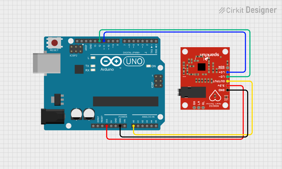
Example: Connecting AD8232 to Arduino UNO
Below is an example of how to connect the AD8232 to an Arduino UNO and read the ECG signal:
Wiring
- Connect the 3.3V pin of the AD8232 to the 3.3V pin on the Arduino.
- Connect the GND pin of the AD8232 to the GND pin on the Arduino.
- Connect the OUTPUT pin of the AD8232 to the A0 analog input pin on the Arduino.
- Connect the electrodes to the RA, LA, and RL pins as described above.
Arduino Code
// AD8232 ECG Module Example Code
// Reads the ECG signal from the AD8232 module and outputs it via Serial Monitor.

const int ecgPin = A0; // Analog pin connected to AD8232 OUTPUT pin

void setup() {
  Serial.begin(9600); // Initialize serial communication at 9600 baud
  pinMode(ecgPin, INPUT); // Set the ECG pin as input
}

void loop() {
  int ecgValue = analogRead(ecgPin); // Read the analog value from the ECG pin
  Serial.println(ecgValue); // Print the ECG value to the Serial Monitor
  delay(1); // Small delay for stable readings
}
Notes:
- Open the Arduino Serial Monitor to view the ECG signal values in real-time.
- Use a plotting tool (e.g., Arduino Serial Plotter) to visualize the ECG waveform.
Troubleshooting and FAQs
Common Issues and Solutions
No Output Signal:
- Ensure the module is powered correctly (3.3V supply).
- Verify that the electrodes are properly connected and placed on the body.
- Check the wiring between the module and the microcontroller.
Noisy or Distorted Signal:
- Ensure the electrodes are securely attached to the skin.
- Minimize movement during signal acquisition to reduce artifacts.
- Use shielded cables to reduce electromagnetic interference.
Leads-Off Detection Not Working:
- Verify the connections to the LO+ and LO- pins.
- Ensure the electrodes are properly attached to the body.
Module Not Responding:
- Check the SDN pin. Ensure it is pulled low to activate the module.
- Verify all connections and ensure there are no loose wires.
FAQs
Q: Can the AD8232 be powered with 5V?
A: No, the AD8232 is designed to operate with a supply voltage between 2.0V and 3.5V. Using 5V may damage the module.
Q: How do I visualize the ECG waveform?
A: You can use the Arduino Serial Plotter or an external oscilloscope to visualize the ECG signal.
Q: Can I use the AD8232 for other biopotential measurements?
A: Yes, the AD8232 can be used for other biopotential signals, but additional configuration may be required for optimal performance.
Q: What is the typical range of the output signal?
A: The output signal typically ranges from 0V to the supply voltage (e.g., 0V to 3.3V).