How to Use Mini 360 Buck Converter: Examples, Pinouts, and Specs
Introduction
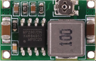
The Mini 360 Buck Converter is a compact DC-DC step-down voltage regulator designed to efficiently reduce a higher input voltage to a lower output voltage. This component is widely used in applications where space is limited, and efficient power conversion is required. Its small size and high efficiency make it ideal for powering low-voltage devices such as microcontrollers, sensors, and other electronic modules.
Explore Projects Built with Mini 360 Buck Converter


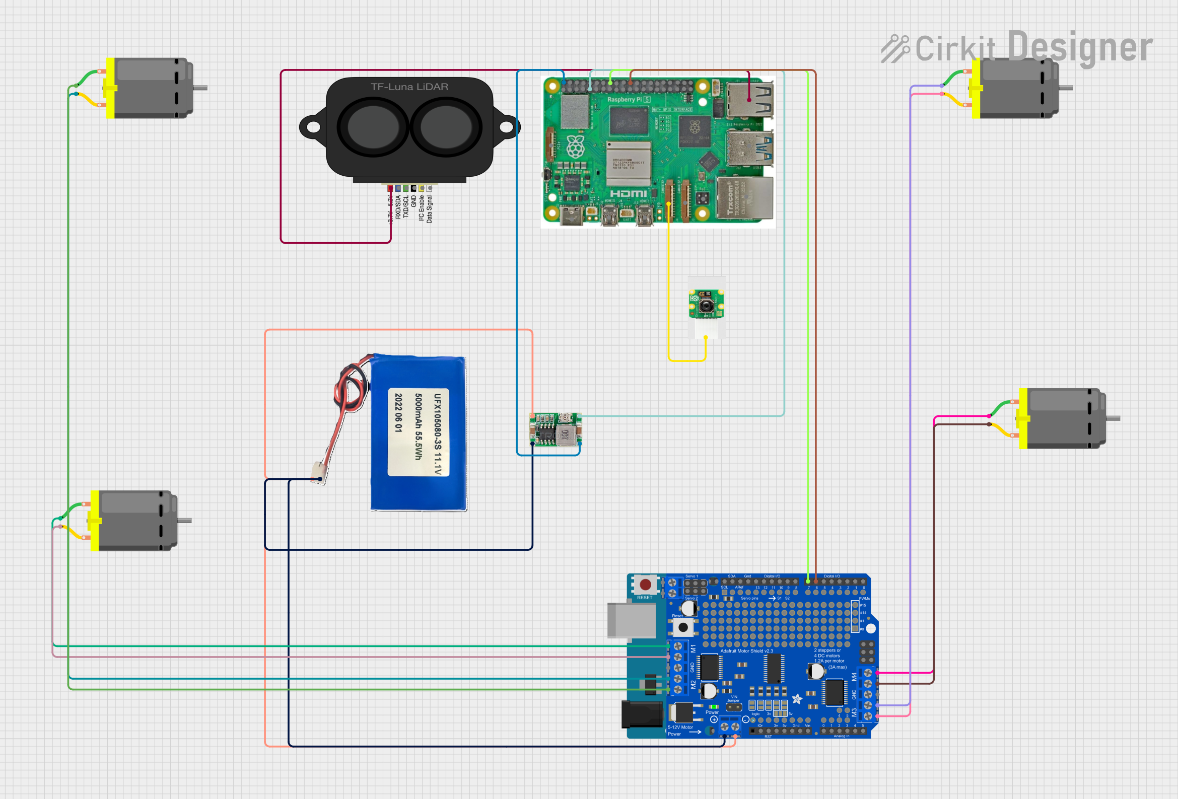
Explore Projects Built with Mini 360 Buck Converter
Common Applications and Use Cases
- Powering low-voltage microcontrollers (e.g., Arduino, ESP32, Raspberry Pi peripherals)
- Battery-powered projects requiring efficient voltage regulation
- Converting 12V or 24V power sources to 5V or 3.3V for sensors and modules
- DIY electronics and prototyping
- Automotive electronics for powering USB devices or low-voltage circuits
Technical Specifications
The Mini 360 Buck Converter is a highly efficient and versatile voltage regulator. Below are its key technical details:
| Parameter | Specification |
|---|---|
| Input Voltage Range | 4.75V to 23V |
| Output Voltage Range | 1.0V to 17V (adjustable via potentiometer) |
| Maximum Output Current | 1.8A (continuous), 3A (peak) |
| Efficiency | Up to 96% |
| Switching Frequency | 340 kHz |
| Dimensions | 17 mm x 11 mm x 3.8 mm |
| Operating Temperature | -40°C to +85°C |
Pin Configuration and Descriptions
The Mini 360 Buck Converter has four main pins for input and output connections:
| Pin Name | Description |
|---|---|
| VIN | Positive input voltage (4.75V to 23V) |
| GND | Ground (common for input and output) |
| VOUT | Positive output voltage (adjustable, 1.0V-17V) |
| GND | Ground (common for input and output) |
Usage Instructions
How to Use the Mini 360 Buck Converter in a Circuit
Connect the Input Voltage:
- Connect the positive terminal of your power source to the
VINpin. - Connect the negative terminal of your power source to the
GNDpin.
- Connect the positive terminal of your power source to the
Adjust the Output Voltage:
- Use a small screwdriver to turn the onboard potentiometer.
- Turning clockwise increases the output voltage, while turning counterclockwise decreases it.
- Measure the output voltage across the
VOUTandGNDpins using a multimeter to ensure it matches your desired value.
Connect the Load:
- Connect the positive terminal of your load to the
VOUTpin. - Connect the negative terminal of your load to the
GNDpin.
- Connect the positive terminal of your load to the
Verify Connections:
- Double-check all connections to ensure proper polarity and avoid short circuits.
Important Considerations and Best Practices
- Input Voltage Range: Ensure the input voltage is within the specified range (4.75V to 23V). Exceeding this range may damage the converter.
- Output Voltage Adjustment: Always measure the output voltage with a multimeter before connecting your load to avoid overvoltage damage.
- Heat Dissipation: For high-current applications, ensure proper ventilation or add a heatsink to prevent overheating.
- Load Current: Do not exceed the maximum continuous output current of 1.8A to avoid damaging the converter.
- Polarity: Double-check the polarity of your connections to prevent reverse polarity damage.
Example: Using the Mini 360 Buck Converter with an Arduino UNO
To power an Arduino UNO with a 5V supply using the Mini 360 Buck Converter:
- Connect a 12V DC power source to the
VINandGNDpins of the converter. - Adjust the output voltage to 5V using the potentiometer.
- Connect the
VOUTpin to the Arduino's 5V pin and theGNDpin to the Arduino's GND pin.
Here is an example Arduino code to blink an LED, assuming the Mini 360 Buck Converter is powering the Arduino:
// Simple LED Blink Example
// Ensure the Mini 360 Buck Converter is set to 5V output before powering the Arduino.

const int ledPin = 13; // Built-in LED pin on Arduino UNO

void setup() {
  pinMode(ledPin, OUTPUT); // Set the LED pin as an output
}

void loop() {
  digitalWrite(ledPin, HIGH); // Turn the LED on
  delay(1000);                // Wait for 1 second
  digitalWrite(ledPin, LOW);  // Turn the LED off
  delay(1000);                // Wait for 1 second
}
Troubleshooting and FAQs
Common Issues and Solutions
No Output Voltage:
- Cause: Incorrect input connections or insufficient input voltage.
- Solution: Verify the input voltage is within the specified range and check the polarity of the connections.
Output Voltage Fluctuates:
- Cause: Load current exceeds the maximum rating or unstable input voltage.
- Solution: Reduce the load current or stabilize the input voltage with a capacitor.
Overheating:
- Cause: High load current or poor ventilation.
- Solution: Reduce the load current or add a heatsink to the converter.
Cannot Adjust Output Voltage:
- Cause: Faulty potentiometer or incorrect adjustment.
- Solution: Ensure the potentiometer is not damaged and adjust it carefully.
FAQs
Q: Can the Mini 360 Buck Converter step up voltage?
A: No, the Mini 360 is a step-down (buck) converter and cannot increase the input voltage.Q: What is the maximum input voltage?
A: The maximum input voltage is 23V. Exceeding this value may damage the converter.Q: Can I use the Mini 360 Buck Converter with a battery?
A: Yes, it is suitable for battery-powered applications as long as the input voltage is within the specified range.Q: How do I know if the converter is overheating?
A: If the converter becomes too hot to touch or shuts down intermittently, it may be overheating. Reduce the load or improve cooling.
By following this documentation, you can effectively use the Mini 360 Buck Converter in your projects and troubleshoot common issues.