
How to Use XBee Explorer Regulated: Examples, Pinouts, and Specs

 Design with XBee Explorer Regulated in Cirkit Designer
Introduction
The XBee Explorer Regulated is a development board designed to simplify the use of XBee modules in wireless communication projects. It provides a regulated power supply and easy access to the XBee module's pins, making it ideal for prototyping and testing. This board is particularly useful for interfacing XBee modules with microcontrollers, such as Arduino, or for standalone wireless communication setups.
Explore Projects Built with XBee Explorer Regulated
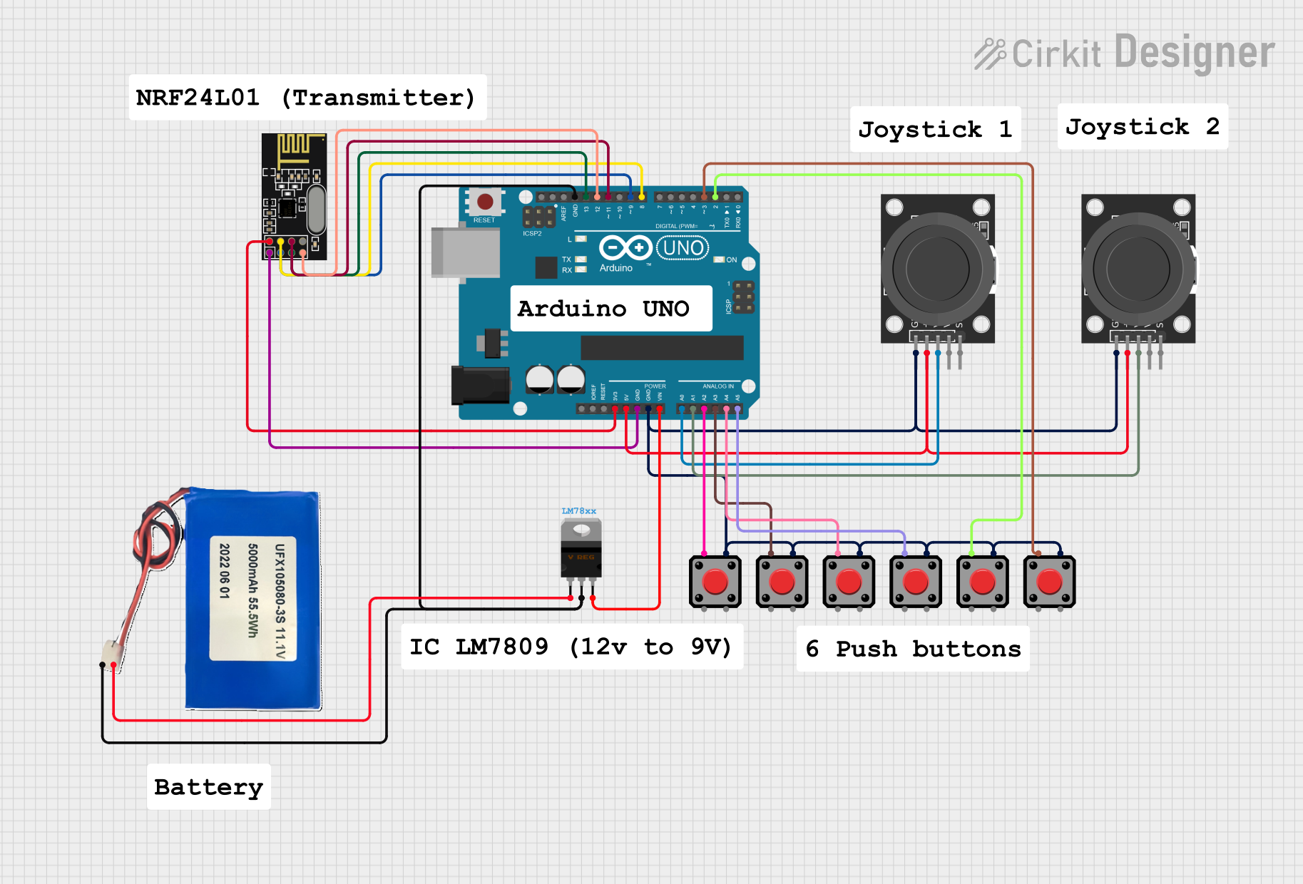 Open Project in Cirkit Designer
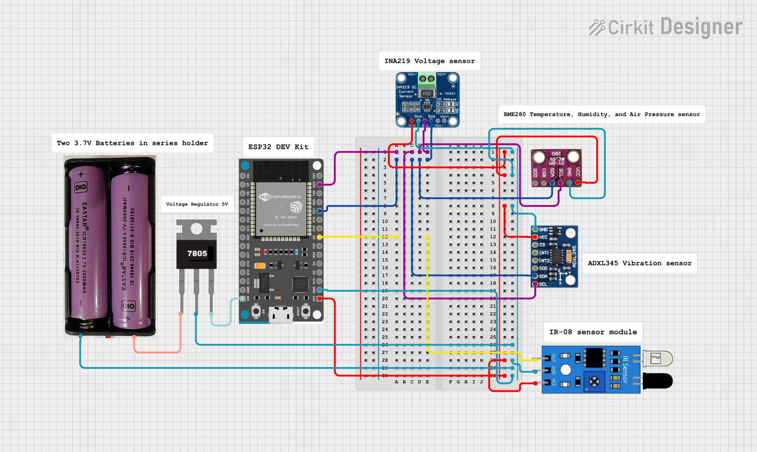 Open Project in Cirkit Designer
 Open Project in Cirkit Designer
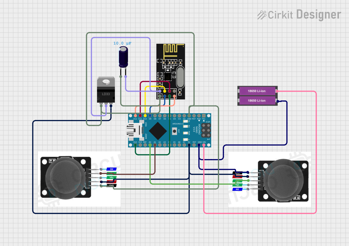 Open Project in Cirkit Designer
Explore Projects Built with XBee Explorer Regulated
Open Project in Cirkit DesignerOpen Project in Cirkit DesignerOpen Project in Cirkit DesignerOpen Project in Cirkit DesignerCommon Applications and Use Cases
- Wireless sensor networks
- Home automation systems
- Remote data logging
- Robotics and IoT projects
- Prototyping and testing XBee-based communication systems
Technical Specifications
The XBee Explorer Regulated is designed to work seamlessly with XBee modules, offering the following key specifications:
Key Technical Details
| Parameter | Specification |
|---|---|
| Input Voltage Range | 3.3V to 16V DC |
| Output Voltage to XBee | 3.3V DC (regulated) |
| Maximum Current Output | 250mA |
| Communication Interface | UART (TX, RX) |
| Onboard LEDs | Power, RSSI (Signal Strength), TX, RX |
| Dimensions | 1.3" x 1.0" (33mm x 25mm) |
Pin Configuration and Descriptions
| Pin Name | Description |
|---|---|
| VCC | Input voltage pin (3.3V to 16V DC). Powers the board and the XBee module. |
| GND | Ground connection. |
| TX | Transmit pin. Sends data from the XBee module to the connected device. |
| RX | Receive pin. Receives data from the connected device to the XBee module. |
| DOUT | Digital output pin from the XBee module. |
| DIN | Digital input pin to the XBee module. |
| RSSI LED | Indicates the signal strength of the XBee module. |
| TX LED | Lights up when data is transmitted from the XBee module. |
| RX LED | Lights up when data is received by the XBee module. |
Usage Instructions
How to Use the XBee Explorer Regulated in a Circuit
- Power the Board: Connect a DC power source (3.3V to 16V) to the VCC and GND pins.
- Insert the XBee Module: Align the XBee module's pins with the socket on the board and gently press it into place.
- Connect to a Microcontroller:
- Use the TX and RX pins to connect the XBee Explorer Regulated to the UART pins of your microcontroller (e.g., Arduino UNO).
- Ensure proper voltage level matching if connecting to a 5V microcontroller.
- Monitor LEDs:
- The power LED indicates the board is powered.
- The RSSI LED provides feedback on signal strength.
- The TX and RX LEDs indicate data transmission and reception.
- Program and Test:
- Configure the XBee module using XCTU software or AT commands.
- Test communication between two XBee modules or between the XBee and a microcontroller.
Important Considerations and Best Practices
- Voltage Levels: Ensure the input voltage does not exceed 16V to avoid damaging the board.
- Antenna Placement: For optimal wireless performance, position the XBee module's antenna away from metal objects or other sources of interference.
- UART Configuration: Match the baud rate and other UART settings between the XBee module and the connected device.
- Static Protection: Handle the XBee module and Explorer board with care to avoid static discharge damage.
Example: Connecting to an Arduino UNO
Below is an example of how to use the XBee Explorer Regulated with an Arduino UNO for basic communication:
Wiring Diagram
| XBee Explorer Pin | Arduino UNO Pin |
|---|---|
| TX | RX (Pin 0) |
| RX | TX (Pin 1) |
| VCC | 5V |
| GND | GND |
Arduino Code
// Example code for sending and receiving data with XBee Explorer Regulated
// connected to an Arduino UNO

void setup() {
  Serial.begin(9600); // Initialize serial communication at 9600 baud
  Serial.println("XBee Explorer Regulated Test");
}

void loop() {
  // Send data to the XBee module
  Serial.println("Hello from Arduino!");
  delay(1000); // Wait for 1 second

  // Check if data is received from the XBee module
  if (Serial.available() > 0) {
    String receivedData = Serial.readString(); // Read incoming data
    Serial.print("Received: ");
    Serial.println(receivedData); // Print received data to Serial Monitor
  }
}
Troubleshooting and FAQs
Common Issues and Solutions
No Power LED:
- Ensure the input voltage is within the 3.3V to 16V range.
- Check the power source and connections.
No Communication Between XBee Modules:
- Verify that both XBee modules are configured with the same PAN ID and baud rate.
- Check the antenna connections and ensure there is no interference.
TX/RX LEDs Not Lighting Up:
- Confirm the TX and RX pins are correctly connected to the microcontroller.
- Ensure the UART settings (baud rate, parity, etc.) match between devices.
Weak Signal Strength:
- Check the RSSI LED for signal strength feedback.
- Reposition the XBee module or antenna to reduce interference.
FAQs
Q: Can I use the XBee Explorer Regulated with a 5V microcontroller?
A: Yes, the board regulates the voltage to 3.3V for the XBee module. However, ensure the TX/RX pins are compatible with 5V logic levels or use a level shifter if needed.
Q: How do I configure the XBee module?
A: Use the XCTU software or send AT commands via a serial terminal to configure the module's settings.
Q: Can I power the board with a USB connection?
A: No, the XBee Explorer Regulated does not have a USB interface. Use an external DC power source within the specified voltage range.
Q: What is the maximum range of the XBee module?
A: The range depends on the specific XBee module used. Refer to the module's datasheet for detailed range specifications.