How to Use 0.96" OLED Dual Colour I2C Display: Examples, Pinouts, and Specs
Introduction
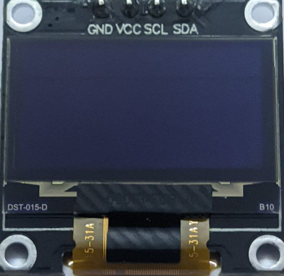
The 0.96" OLED Dual Colour I2C Display is a compact and versatile display module designed for embedded systems. It features a 128x64 pixel resolution and supports dual-color output, typically yellow for the top portion and blue for the bottom. This display uses OLED (Organic Light Emitting Diode) technology, which provides high contrast, wide viewing angles, and low power consumption. Communication is handled via the I2C interface, making it easy to integrate with microcontrollers such as Arduino, Raspberry Pi, and others.
Explore Projects Built with 0.96" OLED Dual Colour I2C Display


Explore Projects Built with 0.96" OLED Dual Colour I2C Display
Common Applications
- Displaying text, graphics, or sensor data in embedded systems
- Wearable devices and portable electronics
- IoT (Internet of Things) projects
- Industrial control panels
- DIY electronics and hobbyist projects
Technical Specifications
| Parameter | Value |
|---|---|
| Display Type | OLED |
| Screen Size | 0.96 inches |
| Resolution | 128x64 pixels |
| Color Output | Dual color (Yellow and Blue) |
| Interface | I2C |
| Operating Voltage | 3.3V - 5V |
| Current Consumption | ~20mA (varies with brightness) |
| Viewing Angle | >160° |
| Operating Temperature | -40°C to +85°C |
| Dimensions | 27mm x 27mm x 4mm |
Pin Configuration
| Pin | Name | Description |
|---|---|---|
| 1 | GND | Ground connection |
| 2 | VCC | Power supply (3.3V or 5V) |
| 3 | SCL | I2C Clock Line |
| 4 | SDA | I2C Data Line |
Usage Instructions
Connecting the Display to an Arduino UNO
To use the 0.96" OLED Dual Colour I2C Display with an Arduino UNO, follow these steps:
Wiring:
- Connect the
GNDpin of the display to theGNDpin on the Arduino. - Connect the
VCCpin of the display to the5Vpin on the Arduino. - Connect the
SCLpin of the display to theA5pin on the Arduino (I2C clock line). - Connect the
SDApin of the display to theA4pin on the Arduino (I2C data line).
- Connect the
Install Required Libraries:
- Open the Arduino IDE.
- Go to
Sketch > Include Library > Manage Libraries. - Search for and install the following libraries:
Adafruit GFX LibraryAdafruit SSD1306
Upload Example Code: Use the following example code to display text on the OLED:
// Include necessary libraries
#include <Wire.h>
#include <Adafruit_GFX.h>
#include <Adafruit_SSD1306.h>

// Define the OLED display width and height
#define SCREEN_WIDTH 128
#define SCREEN_HEIGHT 64

// Create an SSD1306 display object
Adafruit_SSD1306 display(SCREEN_WIDTH, SCREEN_HEIGHT, &Wire, -1);

void setup() {
  // Initialize the display
  if (!display.begin(SSD1306_I2C_ADDRESS, 0x3C)) {
    // Display initialization failed
    Serial.println(F("SSD1306 allocation failed"));
    for (;;); // Halt execution
  }

  // Clear the display buffer
  display.clearDisplay();

  // Set text size and color
  display.setTextSize(1); // Small text size
  display.setTextColor(SSD1306_WHITE);

  // Display text
  display.setCursor(0, 0); // Set cursor to top-left corner
  display.println(F("Hello, OLED!"));
  display.println(F("Dual Color Display"));
  display.display(); // Render the text on the screen
}

void loop() {
  // Nothing to do here
}
Important Considerations
- I2C Address: The default I2C address for most 0.96" OLED displays is
0x3C. If the display does not work, check the address using an I2C scanner sketch. - Power Supply: Ensure the display is powered with the correct voltage (3.3V or 5V). Exceeding the voltage rating may damage the module.
- Contrast and Brightness: Prolonged use at maximum brightness may reduce the lifespan of the OLED.
Troubleshooting and FAQs
Common Issues
The display does not turn on:
- Verify the wiring connections, especially
GNDandVCC. - Ensure the power supply voltage matches the display's requirements.
- Check if the I2C address is correct in the code.
- Verify the wiring connections, especially
Text or graphics are not displayed:
- Confirm that the required libraries (
Adafruit GFXandAdafruit SSD1306) are installed. - Ensure the I2C pins (
SCLandSDA) are correctly connected to the Arduino.
- Confirm that the required libraries (
Flickering or unstable display:
- Check for loose connections in the wiring.
- Reduce the I2C clock speed in the Arduino code if necessary.
FAQs
Can I use this display with a 3.3V microcontroller? Yes, the display supports both 3.3V and 5V logic levels.
How do I change the I2C address? Some OLED modules have solder pads on the back to change the I2C address. Refer to the module's datasheet for details.
Can I display images or custom graphics? Yes, you can use the
Adafruit GFXlibrary to draw shapes, bitmaps, and custom graphics.What is the lifespan of the OLED display? The typical lifespan is around 10,000 to 50,000 hours, depending on usage and brightness settings.
By following this documentation, you can effectively integrate and use the 0.96" OLED Dual Colour I2C Display in your projects.