Cirkit Designer Logo
Cirkit Designer
Your all-in-one circuit design IDE
Home / 
Component Documentation

How to Use MKE-M05 Optocoupler Relay Module: Examples, Pinouts, and Specs

Image of MKE-M05 Optocoupler Relay Module
Cirkit Designer LogoDesign with MKE-M05 Optocoupler Relay Module in Cirkit Designer

Introduction

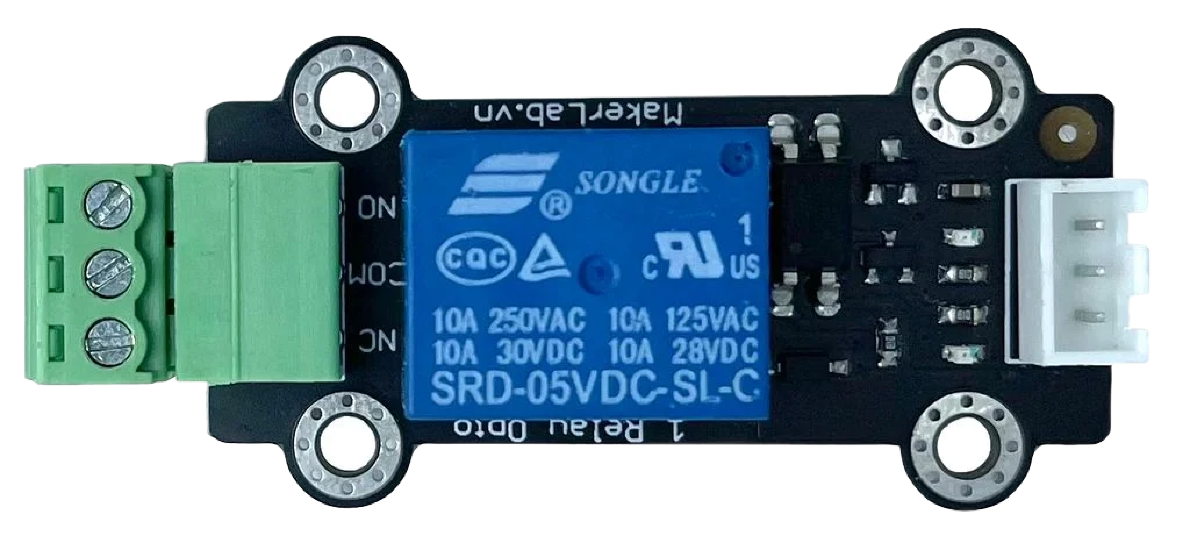
The MKE-M05 Optocoupler Relay Module is an electronic device designed to provide electrical isolation between its input and output while allowing signal control. It uses an optocoupler, also known as an opto-isolator, to transfer signals via light, ensuring that high voltages on the output side do not affect the low voltage input side. This module is commonly used in applications where interfacing low voltage microcontrollers with high voltage circuits is necessary, such as controlling home appliances, industrial machines, and other high-power devices.

Explore Projects Built with MKE-M05 Optocoupler Relay Module

Use Cirkit Designer to design, explore, and prototype these projects online. Some projects support real-time simulation. Click "Open Project" to start designing instantly!
ESP32-S3 Based Smart IoT Distance Sensor with Ethernet Connectivity
Image of ttt: A project utilizing MKE-M05 Optocoupler Relay Module in a practical application
This circuit features an ESP32-S3 microcontroller interfaced with a KY-019 Relay module, a VL53L1X time-of-flight sensor, and a W5500 Ethernet module. The ESP32-S3 controls the relay and communicates with the VL53L1X sensor via I2C, as well as with the network through the Ethernet module. An AC source is converted to DC for powering the components, and a micro USB connection is used to trigger the relay.
Cirkit Designer LogoOpen Project in Cirkit Designer
MakerEdu Creator with Bluetooth, IR Sensors, LCD Display, and Push Button Interaction
Image of MKL Distance Measurement: A project utilizing MKE-M05 Optocoupler Relay Module in a practical application
This circuit features a MakerEdu Creator microcontroller board interfaced with two MKE-S11 IR Infrared Obstacle Avoidance Sensors, a MKE-M02 Push Button Tact Switch, a MKE-M15 Bluetooth module, and a MKE-M08 LCD2004 I2C display module. The push button is connected to a digital input for user interaction, while the IR sensors are likely used for detecting obstacles. The Bluetooth module enables wireless communication, and the LCD display provides a user interface for displaying information or statuses.
Cirkit Designer LogoOpen Project in Cirkit Designer
Arduino Nano Controlled Octocoupler Interface for Signal Isolation
Image of complete togba no lcd: A project utilizing MKE-M05 Optocoupler Relay Module in a practical application
This circuit uses optocouplers paired with 220-ohm resistors to interface an Arduino Nano with an external device via a 5-pin relimate connector, providing electrical isolation and signal transfer while protecting the microcontroller. The Arduino's digital I/O pins are connected to the optocouplers, but the control logic is not yet defined in the provided code.
Cirkit Designer LogoOpen Project in Cirkit Designer
Arduino-Controlled Relay System with Ultrasonic Sensing and Temperature Monitoring
Image of aa: A project utilizing MKE-M05 Optocoupler Relay Module in a practical application
This circuit features an Arduino 101 microcontroller interfaced with a MKE-S01 Ultrasonic Distance Sensor and a temperature sensor (TEMP), used for measuring distance and temperature respectively. The Arduino controls a 4-channel 5V relay module, which in turn manages power to a water pump, two 12V fans, and a WS2815 LED strip. A switching power supply converts 220V AC to a DC voltage, which is then stepped down by an XL4015 DC Buck converter to power the relay module and sensors, while pilot lamps indicate the status of the fans and the LED strip.
Cirkit Designer LogoOpen Project in Cirkit Designer

Explore Projects Built with MKE-M05 Optocoupler Relay Module

Use Cirkit Designer to design, explore, and prototype these projects online. Some projects support real-time simulation. Click "Open Project" to start designing instantly!
Image of ttt: A project utilizing MKE-M05 Optocoupler Relay Module in a practical application
ESP32-S3 Based Smart IoT Distance Sensor with Ethernet Connectivity
This circuit features an ESP32-S3 microcontroller interfaced with a KY-019 Relay module, a VL53L1X time-of-flight sensor, and a W5500 Ethernet module. The ESP32-S3 controls the relay and communicates with the VL53L1X sensor via I2C, as well as with the network through the Ethernet module. An AC source is converted to DC for powering the components, and a micro USB connection is used to trigger the relay.
Cirkit Designer LogoOpen Project in Cirkit Designer
Image of MKL Distance Measurement: A project utilizing MKE-M05 Optocoupler Relay Module in a practical application
MakerEdu Creator with Bluetooth, IR Sensors, LCD Display, and Push Button Interaction
This circuit features a MakerEdu Creator microcontroller board interfaced with two MKE-S11 IR Infrared Obstacle Avoidance Sensors, a MKE-M02 Push Button Tact Switch, a MKE-M15 Bluetooth module, and a MKE-M08 LCD2004 I2C display module. The push button is connected to a digital input for user interaction, while the IR sensors are likely used for detecting obstacles. The Bluetooth module enables wireless communication, and the LCD display provides a user interface for displaying information or statuses.
Cirkit Designer LogoOpen Project in Cirkit Designer
Image of complete togba no lcd: A project utilizing MKE-M05 Optocoupler Relay Module in a practical application
Arduino Nano Controlled Octocoupler Interface for Signal Isolation
This circuit uses optocouplers paired with 220-ohm resistors to interface an Arduino Nano with an external device via a 5-pin relimate connector, providing electrical isolation and signal transfer while protecting the microcontroller. The Arduino's digital I/O pins are connected to the optocouplers, but the control logic is not yet defined in the provided code.
Cirkit Designer LogoOpen Project in Cirkit Designer
Image of aa: A project utilizing MKE-M05 Optocoupler Relay Module in a practical application
Arduino-Controlled Relay System with Ultrasonic Sensing and Temperature Monitoring
This circuit features an Arduino 101 microcontroller interfaced with a MKE-S01 Ultrasonic Distance Sensor and a temperature sensor (TEMP), used for measuring distance and temperature respectively. The Arduino controls a 4-channel 5V relay module, which in turn manages power to a water pump, two 12V fans, and a WS2815 LED strip. A switching power supply converts 220V AC to a DC voltage, which is then stepped down by an XL4015 DC Buck converter to power the relay module and sensors, while pilot lamps indicate the status of the fans and the LED strip.
Cirkit Designer LogoOpen Project in Cirkit Designer

Common Applications and Use Cases

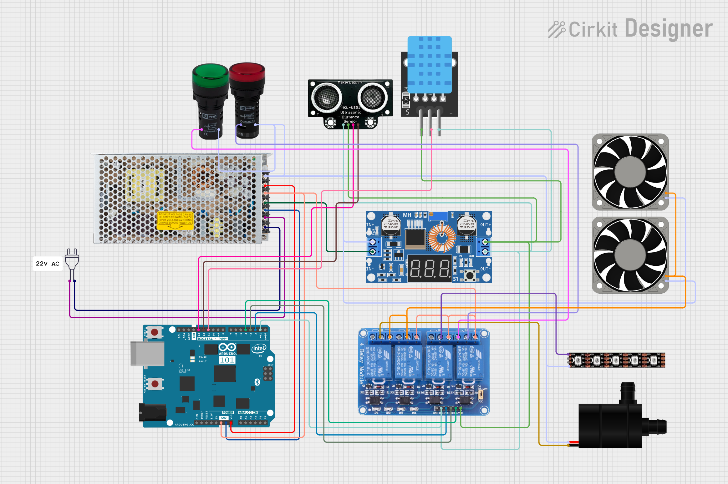
  • Interfacing microcontrollers with high voltage devices
  • Home automation systems
  • Industrial control systems
  • Isolated circuit switching

Technical Specifications

Key Technical Details

  • Input Voltage (Vcc): 3.3V to 5V DC
  • Control Signal Voltage: 3.3V to 5V DC (compatible with most microcontrollers like Arduino)
  • Output Voltage: Up to 250V AC or 30V DC
  • Output Current: Up to 10A (AC) or 10A (DC)
  • Isolation: Optocoupler isolation between input and output circuits

Pin Configuration and Descriptions

Pin Name Description
Vcc Power supply for the module (3.3V to 5V DC)
GND Ground connection
IN Input signal to trigger the relay
NO Normally Open contact of the relay
COM Common contact of the relay
NC Normally Closed contact of the relay

Usage Instructions

How to Use the Component in a Circuit

  1. Connect the Vcc pin to the positive supply of your microcontroller (3.3V or 5V).
  2. Connect the GND pin to the ground of your microcontroller.
  3. Connect the IN pin to a digital output pin of your microcontroller.
  4. Connect the device you wish to control to the NO or NC and COM pins of the relay.

Important Considerations and Best Practices

  • Ensure that the power supply voltage matches the module's requirements.
  • Do not exceed the maximum voltage and current ratings of the relay.
  • Use a flyback diode across the load if inductive loads are being switched to prevent back EMF damage.
  • Always ensure proper isolation when working with high voltages to prevent accidents.

Troubleshooting and FAQs

Common Issues Users Might Face

  • Relay not activating: Check the input signal and power supply connections.
  • Intermittent operation: Ensure that all connections are secure and that there is no intermittent contact.
  • Overheating: Avoid exceeding the current and voltage ratings to prevent overheating.

Solutions and Tips for Troubleshooting

  • Verify that the input signal is within the specified voltage range.
  • Check for any loose connections or potential short circuits.
  • If controlling inductive loads, ensure a flyback diode is in place.

Example Code for Arduino UNO

// Define the relay control pin
const int relayPin = 7;

void setup() {
  // Set the relay pin as an output
  pinMode(relayPin, OUTPUT);
}

void loop() {
  // Turn on the relay
  digitalWrite(relayPin, HIGH);
  delay(1000); // Wait for 1 second
  
  // Turn off the relay
  digitalWrite(relayPin, LOW);
  delay(1000); // Wait for 1 second
}

Note: This example assumes that the IN pin of the MKE-M05 Optocoupler Relay Module is connected to digital pin 7 on the Arduino UNO. The relay will switch on and off every second.

Remember to always follow safety precautions when working with high voltage and current. This documentation is provided for educational purposes and should be applied by experienced individuals or under expert supervision.