How to Use AD627: Examples, Pinouts, and Specs
Introduction
The AD627 is a low-cost, precision instrumentation amplifier designed for high accuracy and low noise applications. It is particularly well-suited for amplifying small differential signals in noisy environments due to its high common-mode rejection ratio (CMRR) and low offset voltage. The AD627 is compact, easy to use, and offers excellent performance, making it a popular choice for a wide range of applications.
Explore Projects Built with AD627

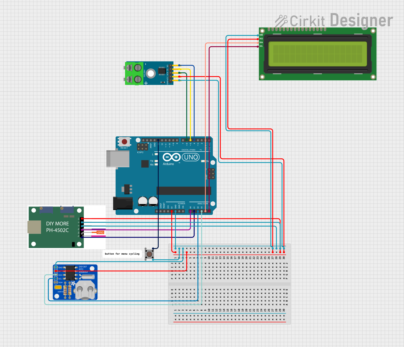
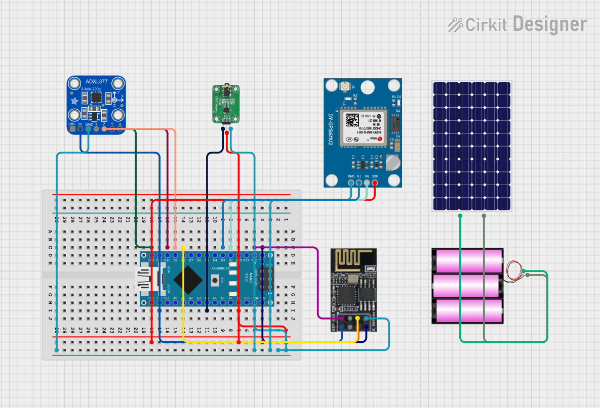
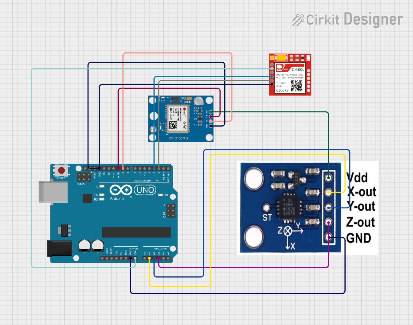
Explore Projects Built with AD627
Common Applications and Use Cases
- Medical instrumentation (e.g., ECG, EEG signal amplification)
- Sensor signal conditioning (e.g., strain gauges, thermocouples)
- Data acquisition systems
- Industrial process controls
- Portable instrumentation
Technical Specifications
Key Technical Details
- Supply Voltage Range: ±2.3 V to ±18 V (or 4.6 V to 36 V single supply)
- Input Offset Voltage: 50 µV (typical)
- Common-Mode Rejection Ratio (CMRR): 100 dB (minimum)
- Gain Range: 5 to 1000 (set by external resistor)
- Input Impedance: 10 GΩ (typical)
- Output Voltage Swing: Rail-to-rail
- Bandwidth: 80 kHz (at G = 5)
- Quiescent Current: 60 µA (typical)
- Package Options: 8-lead SOIC, 8-lead PDIP
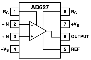
Pin Configuration and Descriptions
The AD627 is available in an 8-pin package. The pinout and descriptions are as follows:
| Pin Number | Pin Name | Description |
|---|---|---|
| 1 | RG | Gain resistor connection. Connect an external resistor to set the gain. |
| 2 | -IN | Inverting input of the amplifier. |
| 3 | +IN | Non-inverting input of the amplifier. |
| 4 | -VS | Negative power supply (or ground for single-supply operation). |
| 5 | REF | Reference voltage input. Sets the output reference voltage. |
| 6 | OUT | Amplifier output. |
| 7 | +VS | Positive power supply. |
| 8 | RG | Gain resistor connection. Connect an external resistor to set the gain. |
Usage Instructions
How to Use the AD627 in a Circuit
- Power Supply: Connect the AD627 to a power supply within the range of ±2.3 V to ±18 V (dual supply) or 4.6 V to 36 V (single supply). Ensure proper decoupling capacitors (e.g., 0.1 µF and 10 µF) are placed close to the power pins.
- Input Connections: Connect the differential signal to the +IN and -IN pins. Ensure the input signal is within the common-mode voltage range of the amplifier.
- Gain Setting: Use an external resistor (RG) between the RG pins (pins 1 and 8) to set the desired gain. The gain is calculated as: [ G = 5 + \frac{200k\Omega}{R_G} ] If no resistor is connected, the default gain is 5.
- Reference Voltage: Connect the REF pin to a reference voltage source (e.g., ground for single-supply operation) to set the output reference voltage.
- Output Connection: The amplified signal is available at the OUT pin. Ensure the load impedance is appropriate for the application.
Important Considerations and Best Practices
- Input Signal Range: Ensure the input signal does not exceed the common-mode voltage range to avoid distortion or clipping.
- Gain Resistor Selection: Use a precision resistor for RG to achieve accurate and stable gain.
- Decoupling Capacitors: Place decoupling capacitors close to the power supply pins to minimize noise and ensure stable operation.
- Output Loading: Avoid driving heavy loads directly from the output. Use a buffer if necessary.
- PCB Layout: Use a clean and low-noise PCB layout. Keep input traces short and away from noisy signals.
Example: Using the AD627 with an Arduino UNO
The AD627 can be used to amplify small sensor signals for an Arduino UNO. Below is an example of interfacing the AD627 with a thermocouple:
Circuit Connections
- Connect the thermocouple's differential output to the +IN and -IN pins of the AD627.
- Set the gain using an external resistor (e.g., 20 kΩ for a gain of 15).
- Connect the REF pin to ground.
- Connect the OUT pin to an analog input pin (e.g., A0) of the Arduino UNO.
Arduino Code
// Example code to read amplified signal from AD627 using Arduino UNO

const int analogPin = A0; // Analog pin connected to AD627 OUT pin
float voltage = 0.0;      // Variable to store the measured voltage
float referenceVoltage = 5.0; // Arduino reference voltage (5V for default)

void setup() {
  Serial.begin(9600); // Initialize serial communication
}

void loop() {
  int adcValue = analogRead(analogPin); // Read ADC value (0-1023)

  // Convert ADC value to voltage
  voltage = (adcValue / 1023.0) * referenceVoltage;

  // Print the measured voltage to the Serial Monitor
  Serial.print("Measured Voltage: ");
  Serial.print(voltage, 3); // Print voltage with 3 decimal places
  Serial.println(" V");

  delay(500); // Wait for 500 ms before the next reading
}
Troubleshooting and FAQs
Common Issues and Solutions
No Output Signal:
- Verify the power supply connections and ensure the AD627 is powered correctly.
- Check the input signal and ensure it is within the common-mode voltage range.
- Confirm that the gain resistor (RG) is properly connected.
Output Clipping:
- Ensure the input signal is not too large for the configured gain.
- Verify that the REF pin is set to an appropriate reference voltage.
Excessive Noise:
- Use proper decoupling capacitors on the power supply pins.
- Ensure the input traces are short and shielded from noise sources.
Incorrect Gain:
- Double-check the value of the external gain resistor (RG).
- Ensure the resistor is a precision type with low tolerance.
FAQs
Q: Can the AD627 operate with a single power supply?
A: Yes, the AD627 can operate with a single supply voltage ranging from 4.6 V to 36 V. Connect the -VS pin to ground in single-supply configurations.
Q: What is the maximum gain I can achieve with the AD627?
A: The maximum gain is 1000, which can be achieved by using an appropriate external resistor for RG.
Q: How do I minimize offset voltage errors?
A: Use precision resistors for gain setting and ensure the REF pin is connected to a stable reference voltage.
Q: Can I use the AD627 for AC signals?
A: Yes, the AD627 can amplify AC signals. However, ensure proper coupling capacitors are used if needed.