How to Use TB6600 DRIVER: Examples, Pinouts, and Specs
Introduction
The TB6600 is a stepper motor driver designed to provide precise control of stepper motors. It supports a wide range of input voltages (up to 40V) and can drive motors with high current ratings (up to 4.5A). This makes it an ideal choice for applications requiring accurate motor control, such as robotics, CNC machinery, 3D printers, and automated systems. The TB6600 is known for its reliability, ease of use, and compatibility with microcontrollers like Arduino and Raspberry Pi.
Common applications and use cases:
- CNC machines for precise motion control
- Robotics for driving stepper motors in robotic arms or mobile platforms
- 3D printers for controlling the movement of print heads and platforms
- Automated conveyor systems in industrial environments
Explore Projects Built with TB6600 DRIVER


Explore Projects Built with TB6600 DRIVER
Technical Specifications
The TB6600 driver is a robust and versatile component. Below are its key technical specifications:
| Parameter | Value |
|---|---|
| Input Voltage | 9V to 40V DC |
| Output Current | Up to 4.5A (adjustable) |
| Microstepping Modes | Full, 1/2, 1/4, 1/8, 1/16 |
| Control Signal Voltage | 3.3V to 5V (logic level) |
| Step Frequency | Up to 200 kHz |
| Operating Temperature | -10°C to +45°C |
| Dimensions | 96mm x 56mm x 33mm |
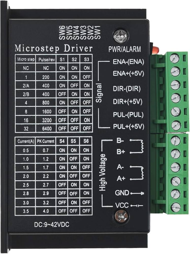
Pin Configuration and Descriptions
The TB6600 driver has several input and output terminals for connecting to a microcontroller, power supply, and stepper motor. Below is the pin configuration:
Input Terminals
| Pin Name | Description |
|---|---|
| PUL+ | Pulse signal input (positive terminal). Used to control the step signal. |
| PUL- | Pulse signal input (negative terminal). Connect to ground. |
| DIR+ | Direction signal input (positive terminal). Determines motor rotation direction. |
| DIR- | Direction signal input (negative terminal). Connect to ground. |
| ENA+ | Enable signal input (positive terminal). Activates or deactivates the driver. |
| ENA- | Enable signal input (negative terminal). Connect to ground. |
Output Terminals
| Pin Name | Description |
|---|---|
| A+ | Connect to the A+ terminal of the stepper motor. |
| A- | Connect to the A- terminal of the stepper motor. |
| B+ | Connect to the B+ terminal of the stepper motor. |
| B- | Connect to the B- terminal of the stepper motor. |
Power Terminals
| Pin Name | Description |
|---|---|
| VCC | Connect to the positive terminal of the DC power supply (9V to 40V). |
| GND | Connect to the negative terminal of the DC power supply. |
Usage Instructions
How to Use the TB6600 in a Circuit
Connect the Power Supply:
- Attach the positive terminal of the DC power supply to the
VCCpin. - Attach the negative terminal of the DC power supply to the
GNDpin.
- Attach the positive terminal of the DC power supply to the
Connect the Stepper Motor:
- Connect the stepper motor's A+ and A- wires to the
A+andA-pins, respectively. - Connect the stepper motor's B+ and B- wires to the
B+andB-pins, respectively.
- Connect the stepper motor's A+ and A- wires to the
Connect to a Microcontroller:
- Connect the
PUL+,DIR+, andENA+pins to the appropriate digital output pins on the microcontroller. - Connect the
PUL-,DIR-, andENA-pins to the ground (GND) of the microcontroller.
- Connect the
Set the Microstepping and Current:
- Use the DIP switches on the TB6600 to configure the microstepping mode and current limit according to your motor's specifications.
Write Control Code:
- Use a microcontroller (e.g., Arduino) to send pulse and direction signals to the TB6600.
Important Considerations and Best Practices
- Ensure the power supply voltage matches the requirements of both the TB6600 and the stepper motor.
- Avoid exceeding the maximum current rating of the driver to prevent overheating or damage.
- Use a heatsink or cooling fan if the driver operates at high currents for extended periods.
- Double-check the wiring to avoid short circuits or incorrect connections.
- Use shielded cables for long connections to reduce electrical noise.
Example Code for Arduino UNO
Below is an example Arduino sketch to control a stepper motor using the TB6600 driver:
// Define pin connections
const int stepPin = 3;  // Connect to PUL+ on TB6600
const int dirPin = 4;   // Connect to DIR+ on TB6600
const int enPin = 5;    // Connect to ENA+ on TB6600

void setup() {
  // Set pin modes
  pinMode(stepPin, OUTPUT);
  pinMode(dirPin, OUTPUT);
  pinMode(enPin, OUTPUT);

  // Enable the driver
  digitalWrite(enPin, LOW); // LOW enables the driver, HIGH disables it
}

void loop() {
  // Set motor direction
  digitalWrite(dirPin, HIGH); // HIGH for one direction, LOW for the other

  // Generate step pulses
  for (int i = 0; i < 200; i++) { // 200 steps for one revolution (depends on motor)
    digitalWrite(stepPin, HIGH); // Step pulse HIGH
    delayMicroseconds(500);      // Pulse duration (adjust for speed)
    digitalWrite(stepPin, LOW);  // Step pulse LOW
    delayMicroseconds(500);      // Delay between pulses
  }

  // Change direction
  digitalWrite(dirPin, LOW);
  delay(1000); // Wait 1 second before reversing direction
}
Troubleshooting and FAQs
Common Issues and Solutions
Motor Not Moving:
- Cause: Incorrect wiring or loose connections.
- Solution: Double-check all connections, especially the motor and power supply.
Driver Overheating:
- Cause: Exceeding the current limit or insufficient cooling.
- Solution: Adjust the current limit using the DIP switches and add a heatsink or cooling fan.
Motor Vibrates but Does Not Rotate:
- Cause: Incorrect stepper motor wiring.
- Solution: Verify the motor's wiring and ensure the coils are connected to the correct terminals.
Erratic Motor Movement:
- Cause: Electrical noise or incorrect pulse timing.
- Solution: Use shielded cables and ensure proper pulse timing in the control code.
Driver Not Responding to Signals:
- Cause: Incorrect logic level or disabled driver.
- Solution: Ensure the
ENA+pin is set to LOW to enable the driver and verify the control signal voltage matches the driver's requirements.
FAQs
Can the TB6600 drive a unipolar stepper motor?
- No, the TB6600 is designed for bipolar stepper motors only.
What is the maximum step frequency supported?
- The TB6600 supports a maximum step frequency of 200 kHz.
Can I use the TB6600 with a 12V power supply?
- Yes, the TB6600 works with power supplies ranging from 9V to 40V.
Do I need a heatsink for the TB6600?
- A heatsink or cooling fan is recommended if the driver operates at high currents for extended periods.