How to Use ESP32-C3: Examples, Pinouts, and Specs

 Design with ESP32-C3 in Cirkit Designer
Introduction
The ESP32-C3 is a highly integrated, low-power System-on-Chip (SoC) designed by Espressif Systems. It is based on a single-core 32-bit RISC-V processor that can operate at up to 160 MHz. The ESP32-C3 offers a combination of Wi-Fi 4 (802.11n) and Bluetooth 5.0 (LE) capabilities, making it an ideal choice for Internet of Things (IoT) applications, smart home devices, wireless sensors, and other projects that require both processing power and connectivity.
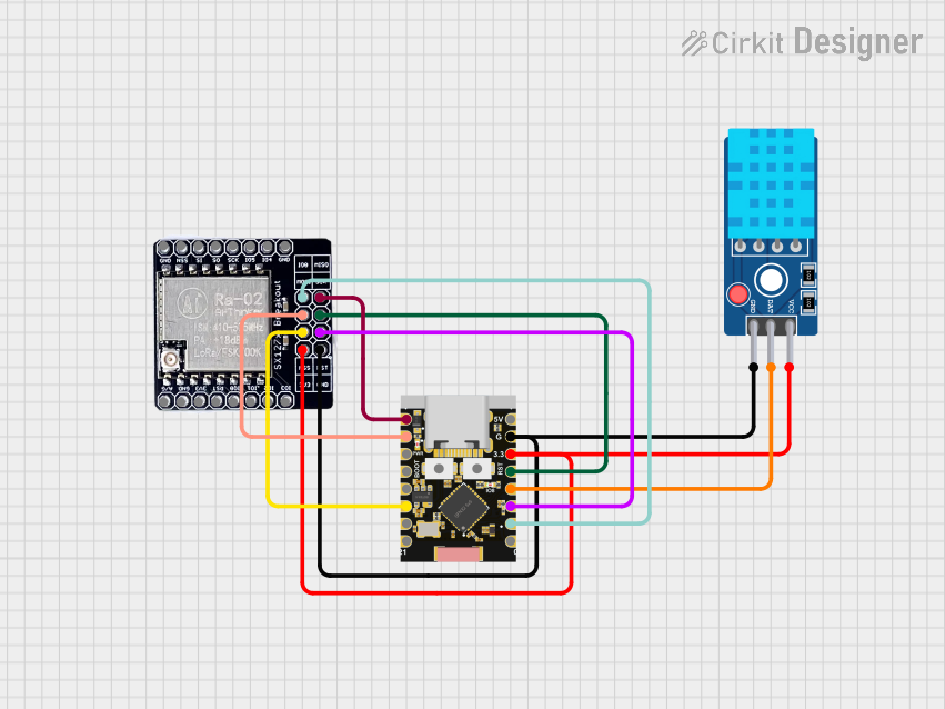
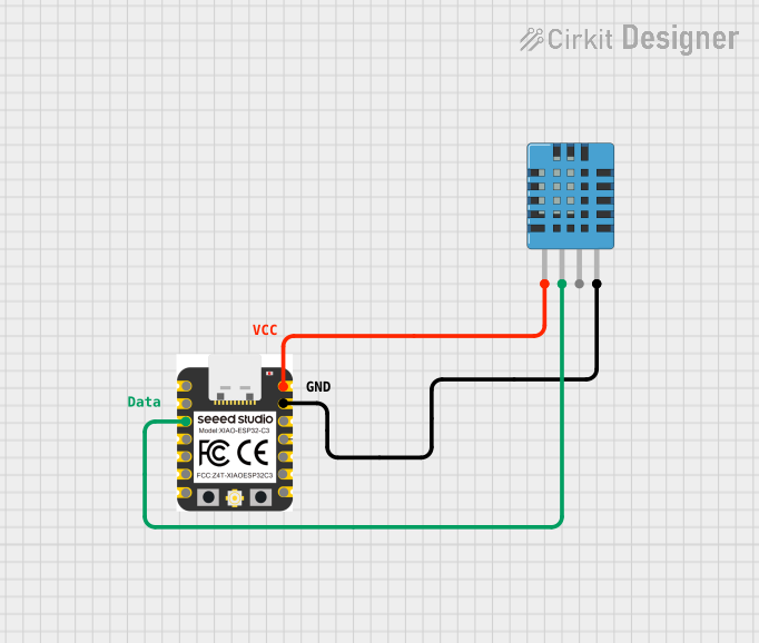
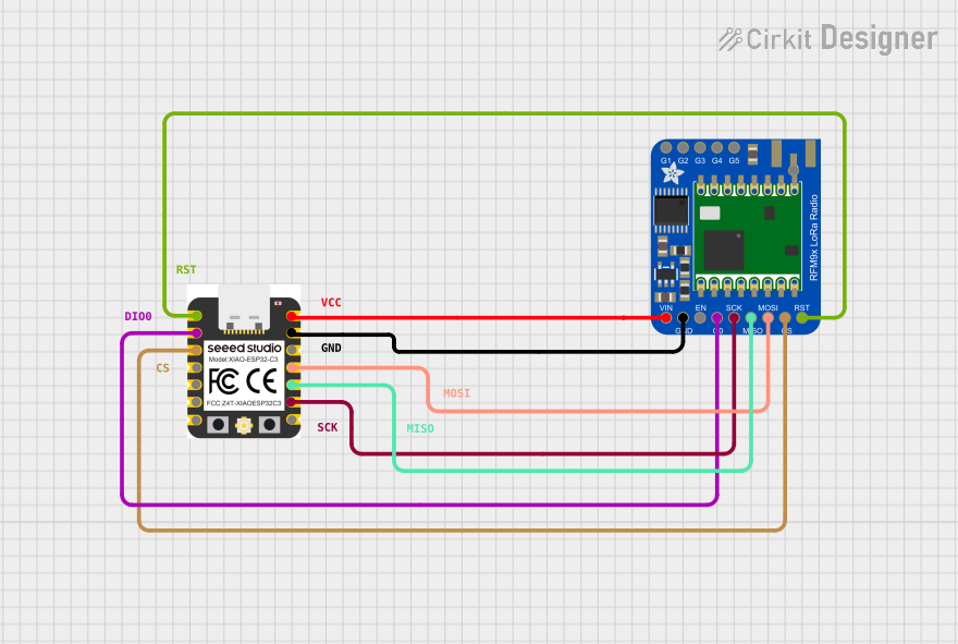
Explore Projects Built with ESP32-C3

 Open Project in Cirkit Designer
 Open Project in Cirkit Designer
 Open Project in Cirkit Designer
 Open Project in Cirkit Designer
Explore Projects Built with ESP32-C3

 Open Project in Cirkit Designer
 Open Project in Cirkit Designer
 Open Project in Cirkit Designer
 Open Project in Cirkit Designer
Common Applications and Use Cases
- Smart home devices (e.g., light switches, thermostats)
- IoT sensors and actuators
- Wearable electronics
- Wireless communication modules
- Low-power embedded systems
Technical Specifications
Key Technical Details
- CPU: Single-core 32-bit RISC-V processor
- Maximum Clock Frequency: 160 MHz
- Memory: 400 KB SRAM, 384 KB ROM
- Flash: External, up to 16 MB
- Wi-Fi: 802.11b/g/n (2.4 GHz)
- Bluetooth: Bluetooth 5.0 LE
- GPIOs: 22
- ADC Channels: 6
- UARTs: 2
- SPIs: 2
- I2Cs: 1
- PWM Channels: 6
- Operating Voltage: 3.0 to 3.6 V
- Operating Temperature: -40°C to 105°C
Pin Configuration and Descriptions
| Pin Number | Name | Type | Description |
|---|---|---|---|
| 1 | GND | P | Ground |
| 2 | 3V3 | P | 3.3V Power Supply |
| 3 | EN | I | Chip Enable (Active High) |
| ... | ... | ... | ... |
| n | IOxx | I/O | General Purpose I/O |
- P: Power
- I: Input
- O: Output
- I/O: Input/Output
Note: This is a simplified representation. The actual ESP32-C3 has multiple functions per pin, and the full datasheet should be consulted for comprehensive pinout information.
Usage Instructions
How to Use the ESP32-C3 in a Circuit
- Power Supply: Connect a stable 3.3V power source to the 3V3 pin and ground to the GND pin.
- Boot Mode: Ensure that the IO0 pin is pulled high during normal operation and low to enter flashing mode.
- Antenna: Connect an appropriate antenna to the antenna pin for Wi-Fi and Bluetooth functionality.
- Programming: Use a USB-to-Serial adapter to connect the UART pins to a computer for programming.
- GPIO: Utilize the GPIO pins for interfacing with sensors, actuators, and other peripherals.
Important Considerations and Best Practices
- Always use a regulated 3.3V power supply to avoid damaging the SoC.
- Avoid exposing the pins to voltages higher than 3.6V.
- Use proper decoupling capacitors close to the power pins to minimize power supply noise.
- Ensure that the antenna design and placement follow the guidelines provided by Espressif to achieve optimal wireless performance.
- Follow ESD precautions when handling the ESP32-C3 to prevent static damage.
Troubleshooting and FAQs
Common Issues
- Device Not Booting: Ensure that the power supply is stable and the EN pin is pulled high.
- Wi-Fi/Bluetooth Not Working: Check the antenna connections and ensure that the software is configured correctly.
- Programming Failures: Verify that IO0 is set low for flashing mode and the UART connections are correct.
Solutions and Tips for Troubleshooting
- Use a multimeter to check for proper voltage levels at the power pins.
- Consult the ESP32-C3 datasheet for detailed pin functions and ensure they are not misconfigured.
- Check for soldering issues or shorts on the PCB if using a custom board design.
FAQs
Q: Can the ESP32-C3 be used with Arduino IDE? A: Yes, the ESP32-C3 can be programmed using the Arduino IDE with the appropriate board support package installed.
Q: What is the maximum range of the Wi-Fi and Bluetooth on the ESP32-C3? A: The range depends on several factors, including the antenna design, obstacles, and interference. Typically, Wi-Fi can reach up to 100 meters in open space, and Bluetooth range is around 10 meters.
Q: How do I update the firmware on the ESP32-C3? A: Firmware can be updated using the UART interface with the device in flashing mode. Tools like esptool.py can be used for flashing.
Example Code for Arduino UNO
Below is an example code snippet for blinking an LED connected to a GPIO pin on the ESP32-C3 using the Arduino IDE. This code assumes that the ESP32-C3 board support package is installed in the Arduino IDE.
// Define the LED pin
const int ledPin = 2; // Replace with the correct GPIO pin number

// Setup function runs once at the start
void setup() {
  // Initialize the LED pin as an output
  pinMode(ledPin, OUTPUT);
}

// Loop function runs repeatedly
void loop() {
  digitalWrite(ledPin, HIGH); // Turn the LED on
  delay(1000);                // Wait for a second
  digitalWrite(ledPin, LOW);  // Turn the LED off
  delay(1000);                // Wait for a second
}
Remember to select the correct board and port in the Arduino IDE before uploading the code to the ESP32-C3.
Note: This documentation provides a basic overview and starting point for working with the ESP32-C3. For more detailed information, always refer to the official datasheets and technical reference manuals provided by Espressif Systems.