Cirkit Designer
Your all-in-one circuit design IDE
Home /
Component Documentation
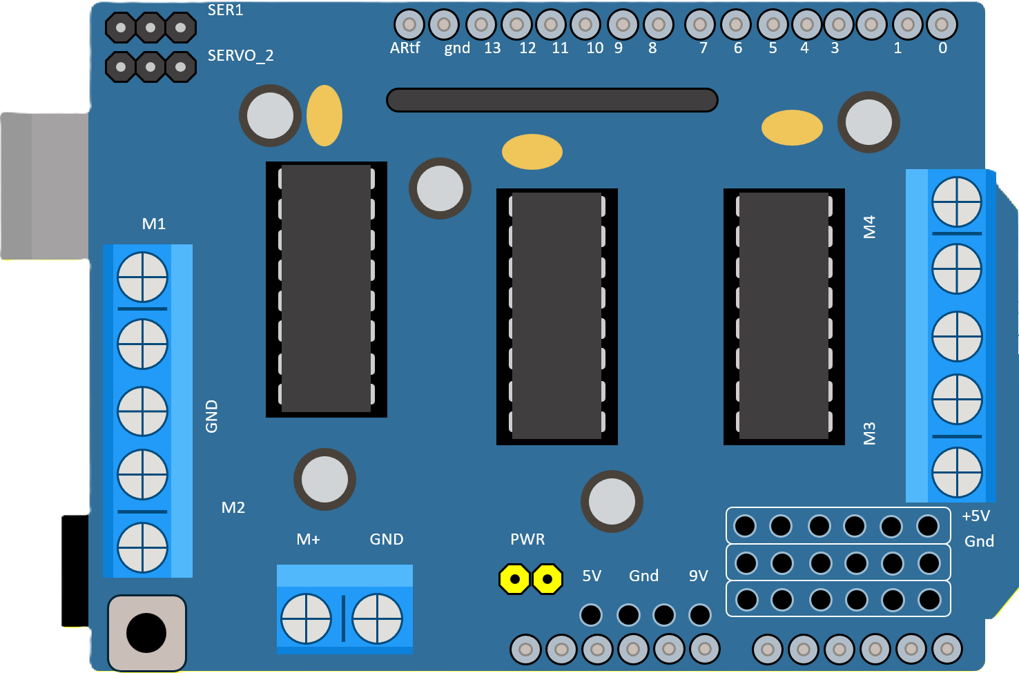
How to Use DRIVER SHIELD L293D: Examples, Pinouts, and Specs
Introduction
The DRIVER SHIELD L293D is a motor driver shield designed for use with the Arduino platform. This shield allows for the control of up to two DC motors, enabling bi-directional rotation and providing the ability to create projects that require motorized movements such as robotics, automated machinery, and more. The L293D shield simplifies the process of controlling motors by integrating H-bridge circuits, which are essential for changing the direction of the motor's rotation.
Explore Projects Built with DRIVER SHIELD L293D
Arduino UNO and L293D Motor Driver Shield for Motor Control
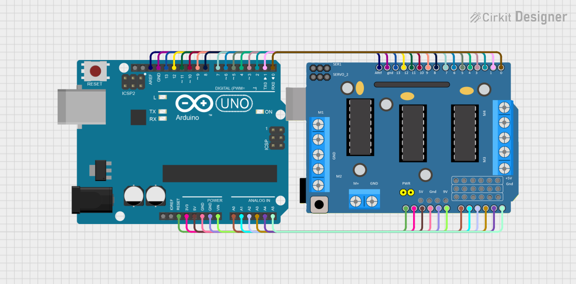
This circuit consists of an Arduino UNO microcontroller connected to a DRIVER SHIELD L293D, which is used to control motors and servos. The shield is powered through the Arduino and all necessary pins are interconnected, allowing the Arduino to manage motor operations via the shield.
Arduino Leonardo and L293D Motor Driver Shield Controlled Robotic System
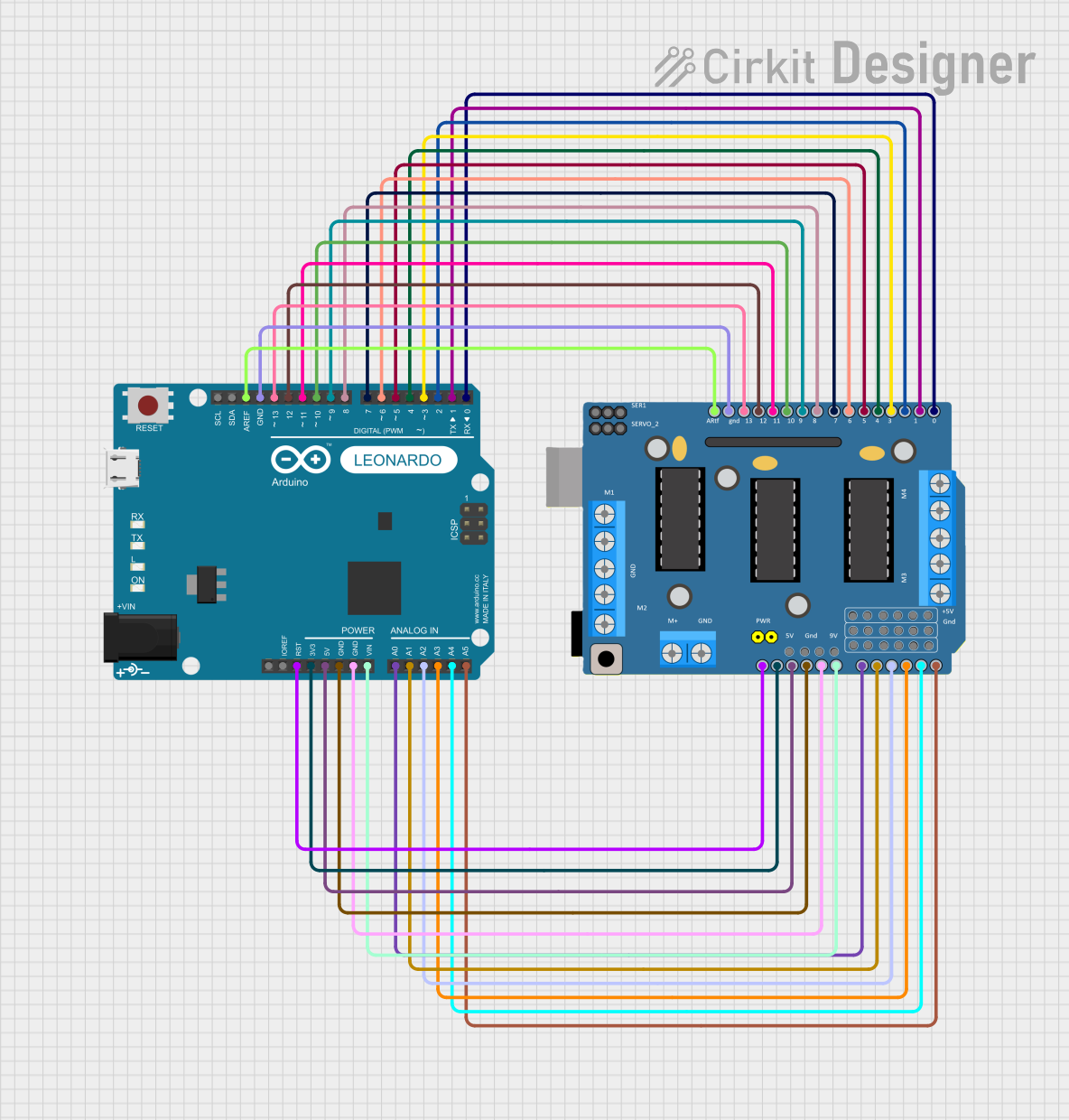
This circuit integrates an Arduino Leonardo with a DRIVER SHIELD L293D to control multiple motors and servos. The Arduino Leonardo provides the processing and control signals, while the DRIVER SHIELD L293D interfaces with the motors and servos, allowing for motor control and power management.
Arduino UNO Controlled Obstacle Avoiding Robot with L293D Motor Driver and Ultrasonic Sensor
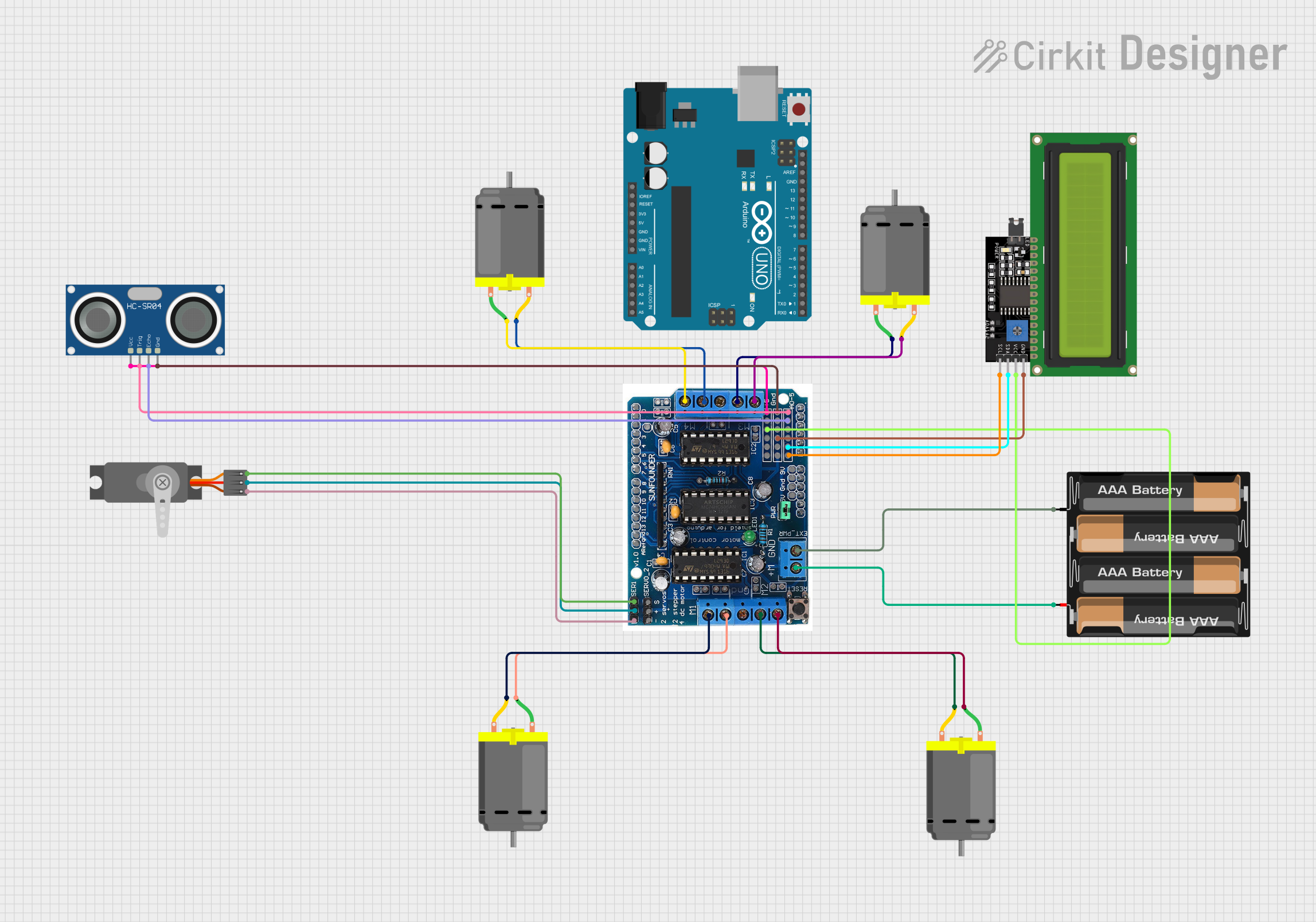
This circuit is designed to control a robot with four DC motors for movement, an ultrasonic sensor for distance measurement, and a servo motor to direct the sensor. The L293D driver shield interfaces with the motors, while the Arduino UNO microcontroller runs the embedded code to process sensor data and control motor speeds and directions. An LCD display is included for output, and power is supplied by a 4 x AAA battery mount.
L293D Motor Driver Shield-Based Autonomous Robot with IR and Ultrasonic Sensors
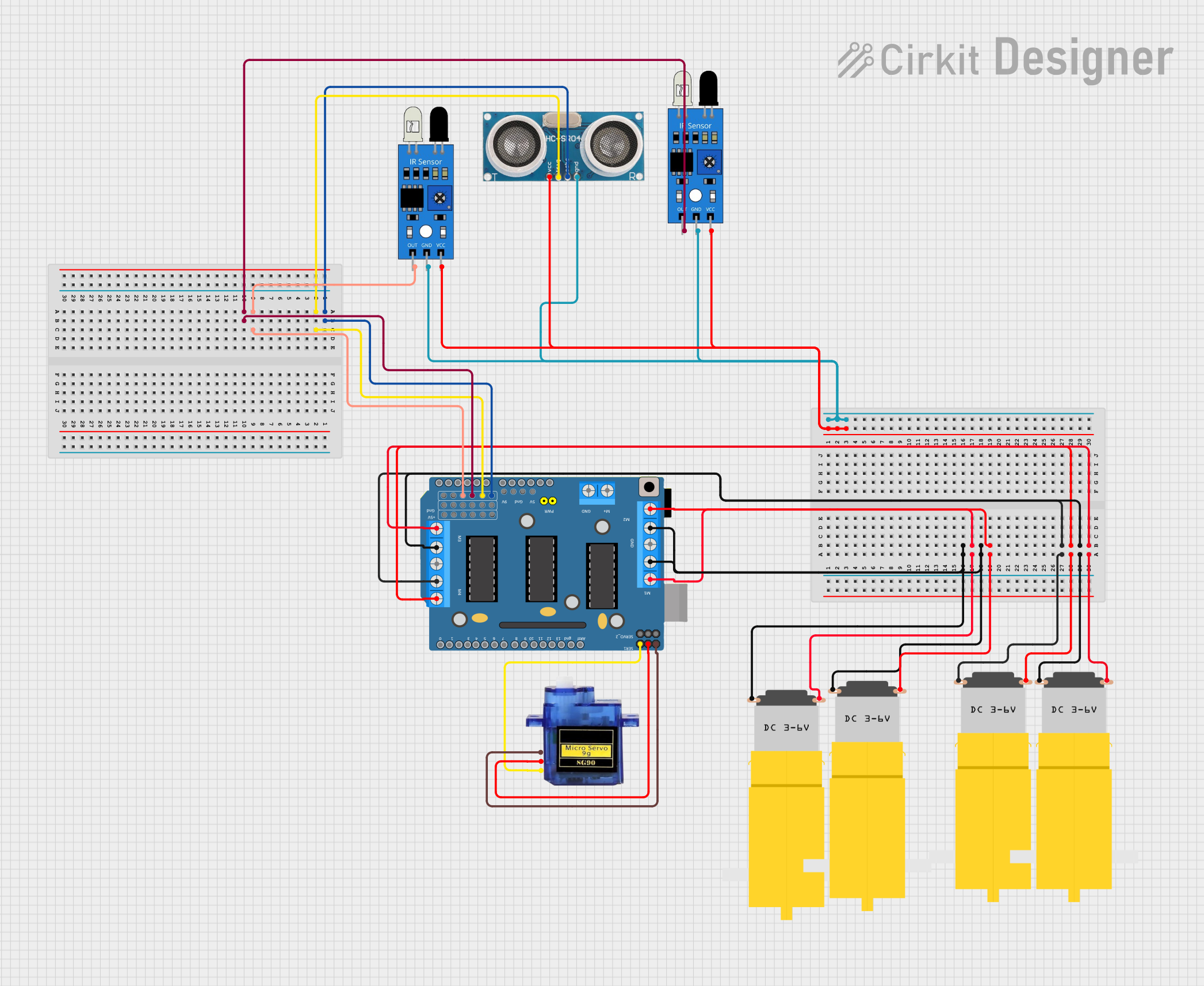
This circuit is designed to control four DC motors and a micro servo using a DRIVER SHIELD L293D. It also includes two IR sensors and an ultrasonic sensor for obstacle detection and distance measurement.
Explore Projects Built with DRIVER SHIELD L293D
Arduino UNO and L293D Motor Driver Shield for Motor Control
This circuit consists of an Arduino UNO microcontroller connected to a DRIVER SHIELD L293D, which is used to control motors and servos. The shield is powered through the Arduino and all necessary pins are interconnected, allowing the Arduino to manage motor operations via the shield.
Arduino Leonardo and L293D Motor Driver Shield Controlled Robotic System
This circuit integrates an Arduino Leonardo with a DRIVER SHIELD L293D to control multiple motors and servos. The Arduino Leonardo provides the processing and control signals, while the DRIVER SHIELD L293D interfaces with the motors and servos, allowing for motor control and power management.
Arduino UNO Controlled Obstacle Avoiding Robot with L293D Motor Driver and Ultrasonic Sensor
This circuit is designed to control a robot with four DC motors for movement, an ultrasonic sensor for distance measurement, and a servo motor to direct the sensor. The L293D driver shield interfaces with the motors, while the Arduino UNO microcontroller runs the embedded code to process sensor data and control motor speeds and directions. An LCD display is included for output, and power is supplied by a 4 x AAA battery mount.
L293D Motor Driver Shield-Based Autonomous Robot with IR and Ultrasonic Sensors
This circuit is designed to control four DC motors and a micro servo using a DRIVER SHIELD L293D. It also includes two IR sensors and an ultrasonic sensor for obstacle detection and distance measurement.
Common Applications and Use Cases
- Robotics: Steering, driving wheels, and actuating robotic limbs.
- Automated systems: Conveyor belts, automated doors, and other machinery.
- Educational projects: Learning about motor control and H-bridge functionality.
- Prototyping: Quick setup for testing motor-driven concepts.
Technical Specifications
Key Technical Details
- Voltage (Motor Supply): 4.5V to 36V
- Voltage (Logic): 5V (from Arduino board)
- Current (Per Channel): 600mA continuous, 1.2A peak
- Channels: 2 (can control 2 DC motors)
- H-Bridge: 4 (2 H-bridges per motor)
Pin Configuration and Descriptions
| Pin Number | Description | Notes |
|---|---|---|
| 1-2 | Motor A Connection | Connect to DC motor A terminals |
| 3-4 | Motor B Connection | Connect to DC motor B terminals |
| 5 | Ground | Connect to Arduino GND |
| 6 | Voltage Supply for Motors (Vm) | 4.5V to 36V |
| 7 | Voltage Supply for Logic (Vss) | 5V from Arduino |
| 8-11 | Control Pins (Input) | Connect to Arduino digital pins |
| 12 | Enable Pin for Motor A | PWM capable for speed control |
| 13 | Enable Pin for Motor B | PWM capable for speed control |
Usage Instructions
How to Use the Component in a Circuit
- Mounting the Shield: Place the L293D shield on top of the Arduino board, ensuring that all pins are aligned and properly inserted.
- Connecting Motors: Connect the terminals of the DC motors to the Motor A and Motor B connections on the shield.
- Power Supply: Provide an external power supply to the Vm pin if the motors require more voltage than the Arduino can supply.
- Control Wiring: Use the control pins to send signals from the Arduino to the L293D shield for motor operation.
- PWM Pins: Connect PWM-capable pins from the Arduino to the enable pins for speed control.
Important Considerations and Best Practices
- Ensure that the power supply voltage and current ratings are within the specifications of the L293D shield to prevent damage.
- Use PWM signals for speed control to enable smooth operation of the motors.
- Always disconnect the power supply before making or altering connections to prevent accidental damage or injury.
- Include flyback diodes if using inductive loads to protect the shield from voltage spikes.
Troubleshooting and FAQs
Common Issues Users Might Face
- Motor not rotating: Check connections, ensure power supply is adequate, and verify that the control signals are being sent correctly.
- Overheating: Ensure that the current draw is within the limits, and consider adding heat sinks if necessary.
- Inconsistent motor speed: Verify that the PWM signal is stable and that the power supply can handle the load without significant voltage drops.
Solutions and Tips for Troubleshooting
- Double-check wiring and solder joints for any loose connections or shorts.
- Use a multimeter to verify the voltage levels at the motor terminals and control pins.
- Test the motors independently to ensure they are functioning correctly.
- Review your code to ensure that the correct pins are being addressed and that the logic is sound.
Example Arduino Code
#include <Arduino.h>

// Define motor control and PWM pins
const int motorAPin1 = 10; // Control pin for motor A
const int motorAPin2 = 9;  // Control pin for motor A
const int motorBPin1 = 11; // Control pin for motor B
const int motorBPin2 = 3;  // Control pin for motor B
const int enablePinA = 5;  // PWM pin for motor A speed
const int enablePinB = 6;  // PWM pin for motor B speed

void setup() {
  // Set motor control pins as outputs
  pinMode(motorAPin1, OUTPUT);
  pinMode(motorAPin2, OUTPUT);
  pinMode(motorBPin1, OUTPUT);
  pinMode(motorBPin2, OUTPUT);
  pinMode(enablePinA, OUTPUT);
  pinMode(enablePinB, OUTPUT);
}

void loop() {
  // Rotate Motor A forward
  digitalWrite(motorAPin1, HIGH);
  digitalWrite(motorAPin2, LOW);
  analogWrite(enablePinA, 128); // Set speed (0-255)

  // Rotate Motor B reverse
  digitalWrite(motorBPin1, LOW);
  digitalWrite(motorBPin2, HIGH);
  analogWrite(enablePinB, 128); // Set speed (0-255)

  delay(2000); // Run motors for 2 seconds

  // Stop motors
  digitalWrite(motorAPin1, LOW);
  digitalWrite(motorAPin2, LOW);
  digitalWrite(motorBPin1, LOW);
  digitalWrite(motorBPin2, LOW);
  analogWrite(enablePinA, 0); // Turn off PWM to stop motor
  analogWrite(enablePinB, 0); // Turn off PWM to stop motor

  delay(1000); // Wait for 1 second
}
This example demonstrates basic forward and reverse control of two DC motors using the L293D motor driver shield. Adjust the analogWrite values to control the speed of the motors.