How to Use TMP102: Examples, Pinouts, and Specs
Introduction
The TMP102 is a digital temperature sensor that communicates via the I2C interface. It provides high-accuracy temperature readings with a range of -40°C to +125°C and features low power consumption, making it ideal for battery-operated devices. The TMP102 is widely used in applications such as environmental monitoring, HVAC systems, medical devices, and consumer electronics. Its small size and ease of integration make it a popular choice for temperature sensing in embedded systems.
Explore Projects Built with TMP102

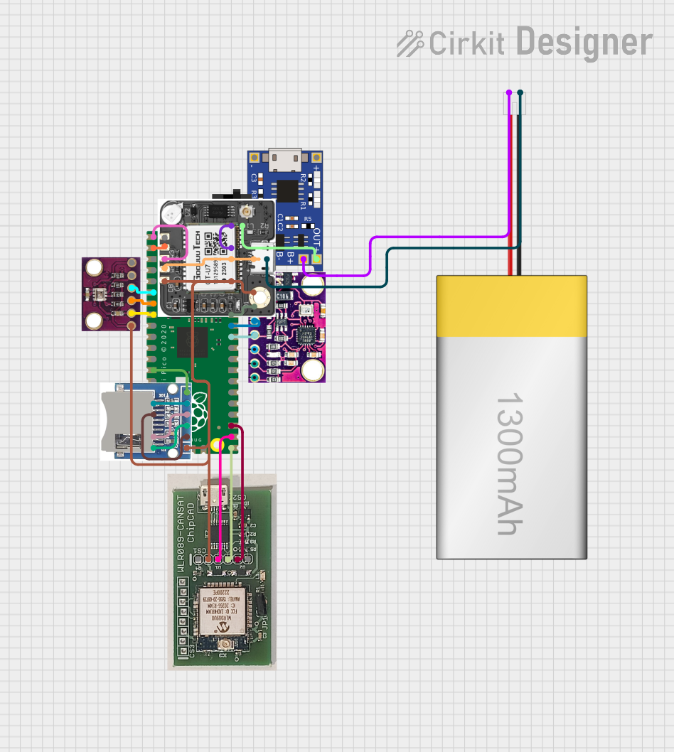
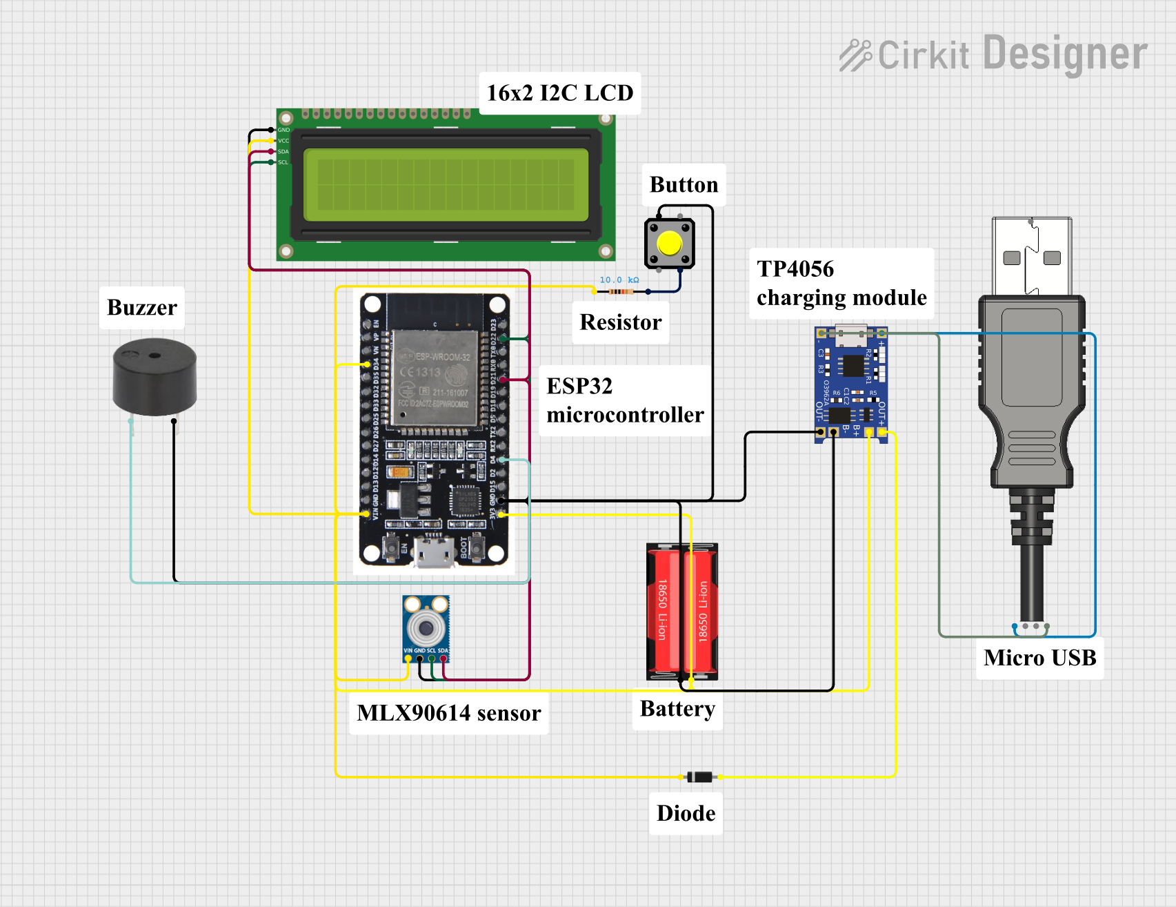

Explore Projects Built with TMP102
Technical Specifications
The TMP102 offers the following key technical details:
| Parameter | Value |
|---|---|
| Supply Voltage (Vcc) | 1.4V to 3.6V |
| Temperature Range | -40°C to +125°C |
| Accuracy | ±0.5°C (typical, -25°C to +85°C) |
| Interface | I2C (2-wire) |
| Resolution | 12-bit (0.0625°C per LSB) |
| Power Consumption | 10 µA (active mode, typical) |
| Shutdown Current | 0.5 µA (typical) |
| I2C Address (default) | 0x48 |
Pin Configuration and Descriptions
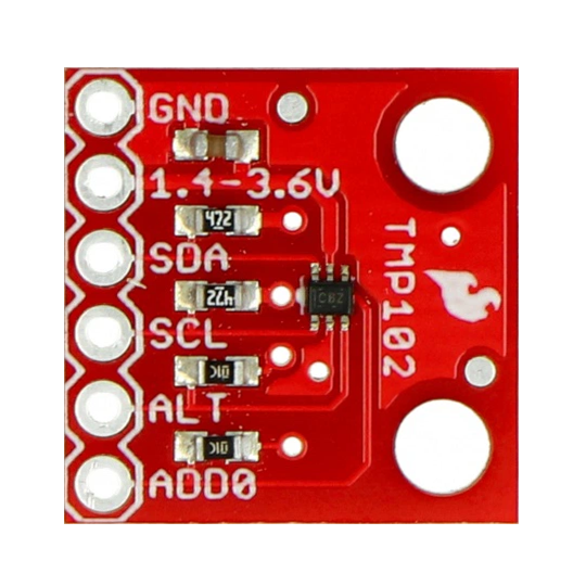
The TMP102 is typically available in an SOT-563 package with the following pinout:
| Pin | Name | Description |
|---|---|---|
| 1 | GND | Ground connection |
| 2 | SDA | Serial Data Line for I2C communication |
| 3 | SCL | Serial Clock Line for I2C communication |
| 4 | ALERT | Alert output for temperature threshold notifications |
| 5 | ADD0 | Address select pin (used to set I2C address) |
| 6 | V+ | Power supply (1.4V to 3.6V) |
Usage Instructions
How to Use the TMP102 in a Circuit
- Power Supply: Connect the V+ pin to a 1.4V to 3.6V power source and the GND pin to ground.
- I2C Communication: Connect the SDA and SCL pins to the corresponding I2C lines of your microcontroller. Use pull-up resistors (typically 4.7kΩ) on both lines.
- Address Configuration: Use the ADD0 pin to set the I2C address:
- Connect ADD0 to GND for address
0x48. - Connect ADD0 to V+ for address
0x49.
- Connect ADD0 to GND for address
- Alert Pin (Optional): The ALERT pin can be used to signal when the temperature exceeds a user-defined threshold. Leave it unconnected if not used.
Important Considerations and Best Practices
- Bypass Capacitor: Place a 0.1 µF ceramic capacitor close to the V+ pin to stabilize the power supply.
- I2C Pull-Up Resistors: Ensure proper pull-up resistors are used on the SDA and SCL lines for reliable communication.
- Temperature Accuracy: For optimal accuracy, avoid placing the TMP102 near heat-generating components.
- Shutdown Mode: Use the shutdown mode to conserve power in battery-operated applications.
Example Code for Arduino UNO
Below is an example of how to interface the TMP102 with an Arduino UNO to read temperature data:
#include <Wire.h> // Include the Wire library for I2C communication

#define TMP102_ADDRESS 0x48 // Default I2C address of the TMP102

void setup() {
  Wire.begin(); // Initialize I2C communication
  Serial.begin(9600); // Start serial communication for debugging
}

void loop() {
  float temperature = readTemperature(); // Read temperature from TMP102
  Serial.print("Temperature: ");
  Serial.print(temperature);
  Serial.println(" °C"); // Print temperature to the serial monitor
  delay(1000); // Wait 1 second before the next reading
}

float readTemperature() {
  Wire.beginTransmission(TMP102_ADDRESS); // Start communication with TMP102
  Wire.write(0x00); // Point to the temperature register
  Wire.endTransmission();

  Wire.requestFrom(TMP102_ADDRESS, 2); // Request 2 bytes of data
  if (Wire.available() == 2) { // Ensure 2 bytes are received
    int msb = Wire.read(); // Most significant byte
    int lsb = Wire.read(); // Least significant byte

    // Combine MSB and LSB, and shift right 4 bits to remove unused bits
    int rawTemperature = ((msb << 8) | lsb) >> 4;

    // Convert raw temperature to Celsius
    float temperature = rawTemperature * 0.0625;
    return temperature;
  } else {
    return NAN; // Return NaN if data is not available
  }
}
Troubleshooting and FAQs
Common Issues and Solutions
No Data from TMP102:
- Cause: Incorrect I2C address or wiring.
- Solution: Verify the ADD0 pin configuration and ensure proper connections to SDA and SCL.
Inaccurate Temperature Readings:
- Cause: Heat from nearby components or insufficient bypass capacitor.
- Solution: Relocate the TMP102 away from heat sources and add a 0.1 µF capacitor near the V+ pin.
I2C Communication Errors:
- Cause: Missing or incorrect pull-up resistors on SDA and SCL lines.
- Solution: Use 4.7kΩ pull-up resistors on both lines.
ALERT Pin Not Functioning:
- Cause: Incorrect configuration of the temperature threshold registers.
- Solution: Refer to the TMP102 datasheet to configure the high and low temperature limits.
FAQs
Q: Can the TMP102 operate at 5V?
A: No, the TMP102 operates within a supply voltage range of 1.4V to 3.6V. Use a voltage regulator if your system operates at 5V.Q: How do I change the I2C address of the TMP102?
A: Use the ADD0 pin to select between two addresses:0x48(ADD0 to GND) or0x49(ADD0 to V+).Q: What is the resolution of the TMP102?
A: The TMP102 provides a 12-bit resolution, corresponding to 0.0625°C per LSB.Q: Can I use multiple TMP102 sensors on the same I2C bus?
A: Yes, but only two sensors can be used since the TMP102 supports two I2C addresses (0x48and0x49). For more sensors, consider using an I2C multiplexer.
This concludes the TMP102 documentation. For further details, refer to the official datasheet.