How to Use Adafruit JTAG 2x10 to SWD 2x5: Examples, Pinouts, and Specs
Introduction
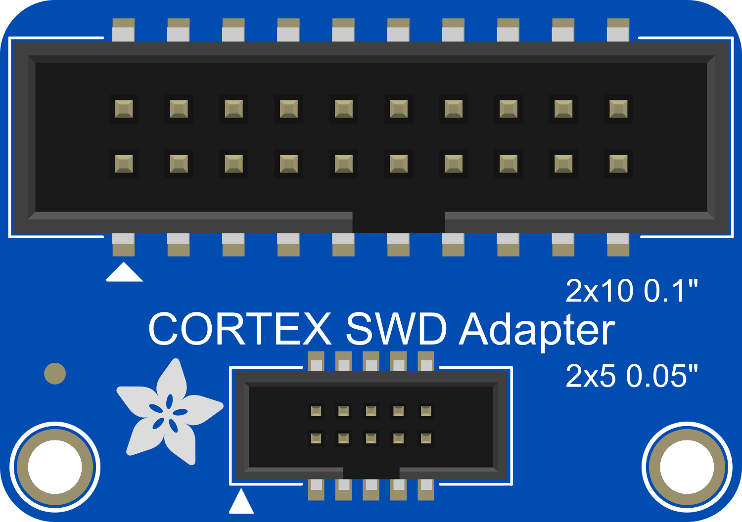
The Adafruit JTAG 2x10 to SWD 2x5 adapter board is a compact and reliable solution designed to bridge the gap between JTAG and Serial Wire Debug (SWD) interfaces. This adapter is particularly useful for developers and engineers who need to debug or program microcontrollers and other ICs that support SWD, but only have access to JTAG tools. Common applications include firmware flashing, debugging embedded systems, and programming microcontrollers in development environments.
Explore Projects Built with Adafruit JTAG 2x10 to SWD 2x5
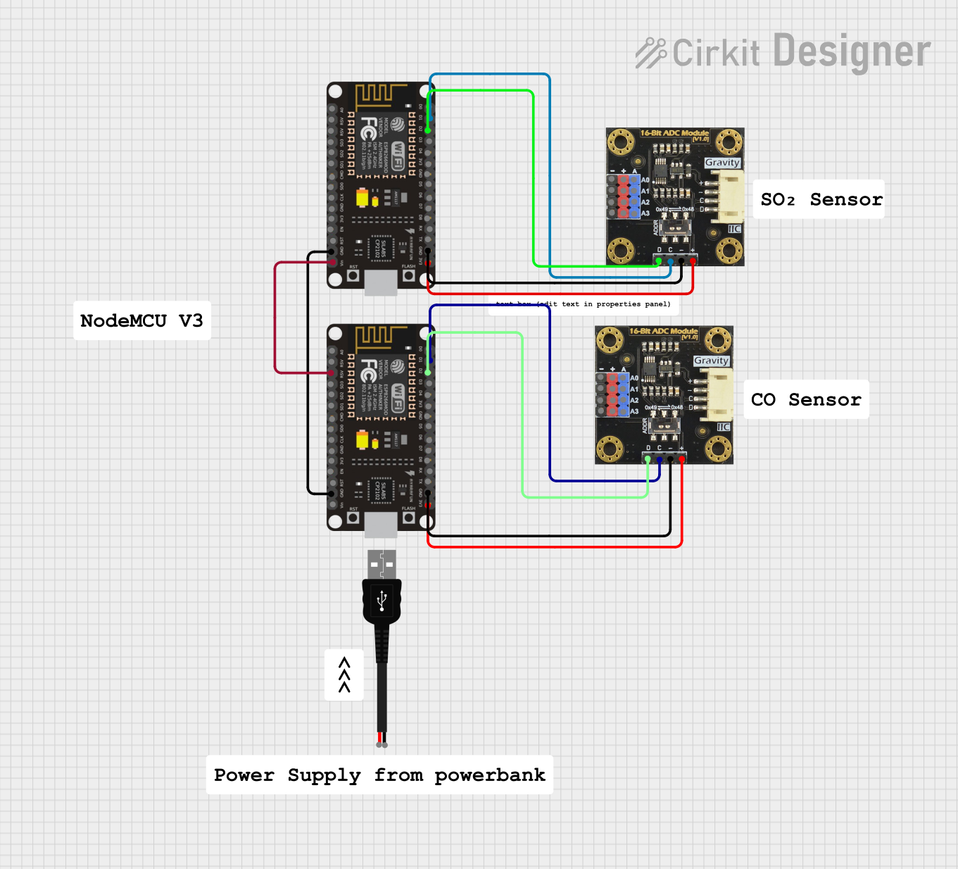
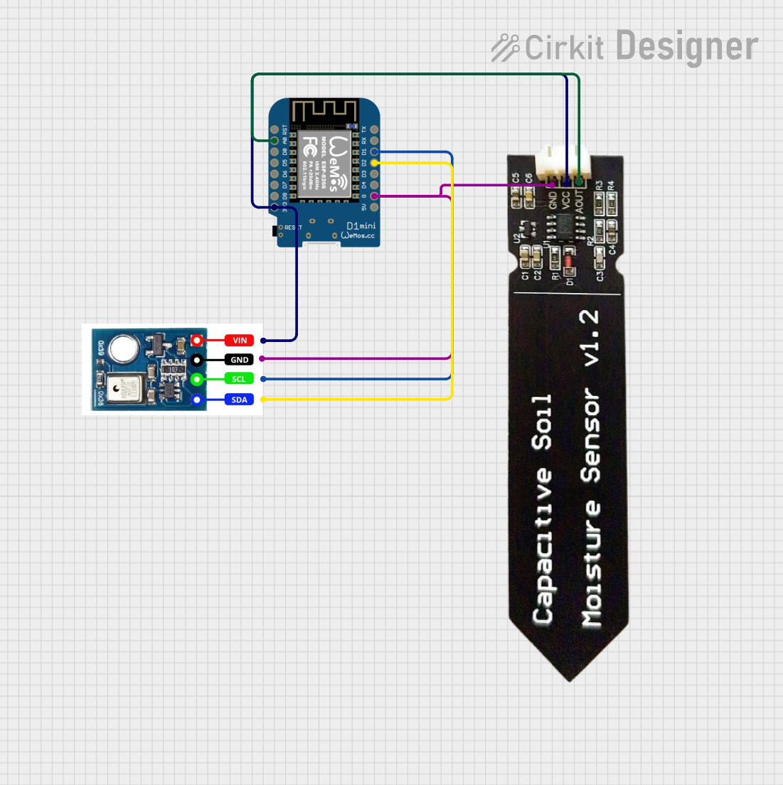

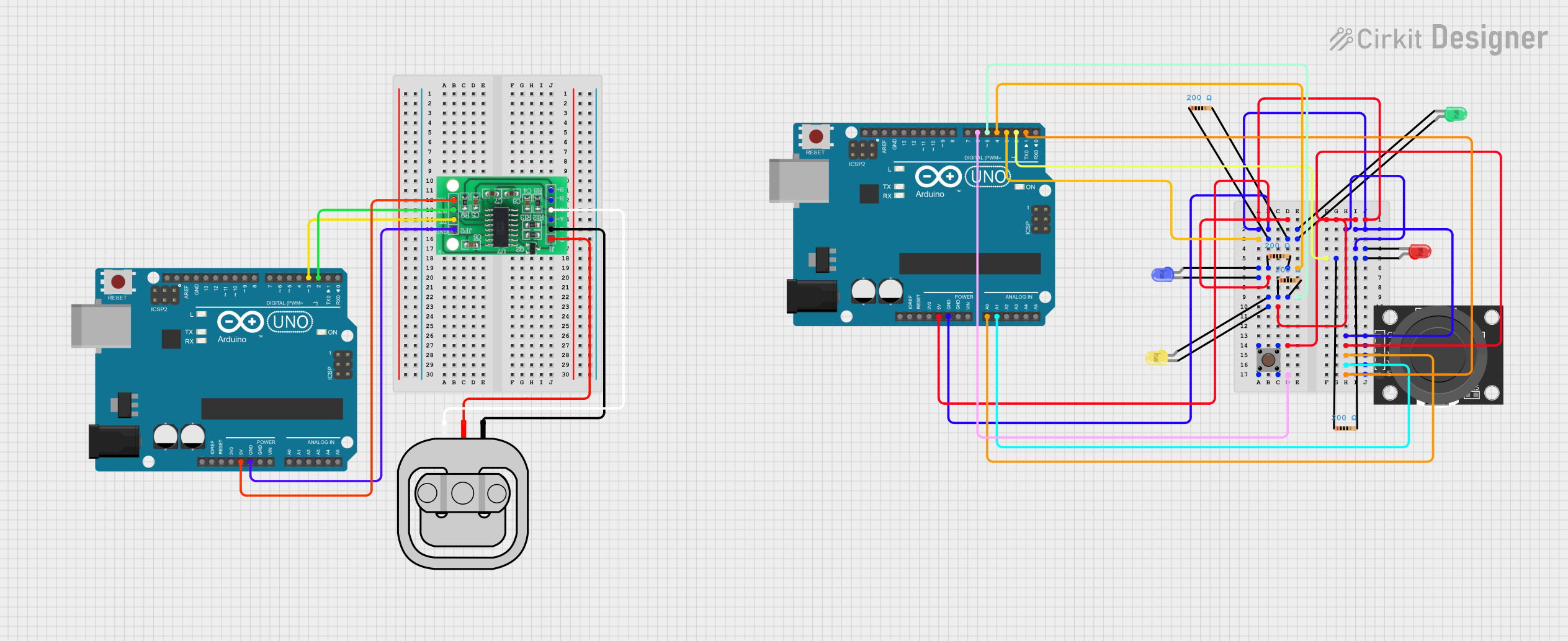
Explore Projects Built with Adafruit JTAG 2x10 to SWD 2x5
Technical Specifications
Key Technical Details
- Dimensions: 0.7" x 0.7" x 0.125" (without headers)
- Weight: 1.3g (without headers)
- JTAG Interface: Standard 2x10 pin (0.1" pitch)
- SWD Interface: Standard 2x5 pin (0.05" pitch)
- Compatibility: Designed to work with devices and development boards that support JTAG and SWD protocols
Pin Configuration and Descriptions
The following tables provide the pinout configurations for the JTAG 2x10 connector and the corresponding SWD 2x5 connector.
JTAG 2x10 Connector Pinout
| Pin # | Signal Name | Description |
|---|---|---|
| 1 | VREF | Target reference voltage |
| 2 | NC | No connection |
| 3 | nTRST | JTAG reset signal (optional) |
| 4 | GND | Ground |
| 5 | TDI | Test Data In |
| 6 | GND | Ground |
| 7 | TMS | Test Mode Select |
| 8 | GND | Ground |
| 9 | TCK | Test Clock |
| 10 | GND | Ground |
| 11 | RTCK | Return Test Clock (optional) |
| 12 | GND | Ground |
| 13 | TDO | Test Data Out |
| 14 | GND | Ground |
| 15 | RESET | System reset signal |
| 16 | GND | Ground |
| 17-20 | NC | No connection |
SWD 2x5 Connector Pinout
| Pin # | Signal Name | Description |
|---|---|---|
| 1 | VREF | Target reference voltage |
| 2 | SWCLK | SWD clock signal |
| 3 | GND | Ground |
| 4 | SWDIO | SWD data I/O |
| 5 | GND | Ground |
| 6 | SWO | Serial Wire Output (optional) |
| 7-10 | NC | No connection |
Usage Instructions
Connecting the Adapter
- Ensure that the target device is powered off before making any connections.
- Align the JTAG 2x10 connector of the adapter board with the JTAG header on your programming tool or debugger.
- Connect the SWD 2x5 connector of the adapter board to the SWD header on the target device.
- Verify that all connections are secure and that the pin orientations match the pinout tables provided above.
Best Practices
- Always handle the adapter board with care to avoid electrostatic discharge (ESD) damage.
- Double-check the pin alignment before powering up the system to prevent damage to the adapter or the target device.
- Use the adapter in a clean and static-free environment.
Troubleshooting and FAQs
Common Issues
Q: The target device is not responding to the debugger. What could be wrong? A: Ensure that all connections are secure and correctly oriented. Check that the target device is powered and that the reference voltage (VREF) is present on the adapter.
Q: I'm getting intermittent connection issues. What should I do? A: Inspect the adapter and the headers for any signs of damage or debris. Clean the contacts if necessary and ensure that the connection is firm.
Q: Can I use this adapter for devices that do not support SWD? A: No, this adapter is specifically designed to convert JTAG to SWD. It will not work with devices that do not support the SWD protocol.
Troubleshooting Tips
- If you encounter issues with the adapter, first verify that the power supply to the target device is stable and within the required voltage range.
- Check for any solder bridges or shorts on the adapter board that may affect the signal integrity.
- Ensure that the firmware and software of your JTAG/SWD debugger are up to date.
For further assistance, contact Adafruit customer support or refer to the community forums for additional troubleshooting advice.