How to Use BTS7960: Examples, Pinouts, and Specs
Introduction
The BTS7960, manufactured by Handson Technology (Part ID: DRV-1012), is a high-current H-bridge motor driver designed for driving DC motors and other inductive loads. It is widely used in applications requiring precise motor control, such as robotics, automation systems, and industrial machinery. The BTS7960 is equipped with built-in protection features, including overcurrent, overtemperature, and undervoltage safeguards, ensuring reliable operation in demanding environments.
Explore Projects Built with BTS7960

Explore Projects Built with BTS7960
Common Applications
- Robotics (e.g., motorized arms, wheeled robots)
- Industrial automation systems
- Electric vehicles and carts
- Conveyor belt systems
- High-power DC motor control
Technical Specifications
Key Technical Details
| Parameter | Value |
|---|---|
| Operating Voltage Range | 5.5V to 27V |
| Maximum Output Current | 43A (continuous) |
| Peak Output Current | 50A |
| Logic Input Voltage | 3.3V to 5V (compatible with most MCUs) |
| PWM Frequency Range | Up to 25kHz |
| Overcurrent Protection | Yes |
| Overtemperature Shutdown | Yes |
| Undervoltage Lockout | Yes |
| Dimensions | 43mm x 43mm x 28mm |
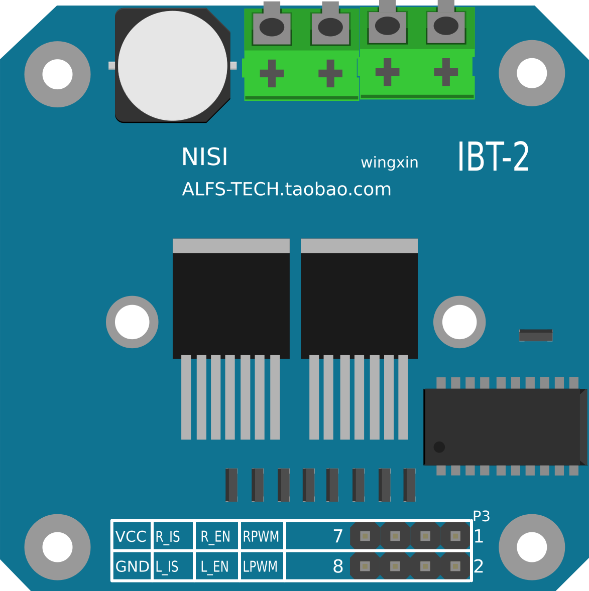
Pin Configuration and Descriptions
The BTS7960 module has a total of 8 pins for interfacing with microcontrollers and power sources. Below is the pinout description:
| Pin Name | Type | Description |
|---|---|---|
| VCC | Power | Logic voltage input (3.3V or 5V) |
| GND | Power | Ground connection for logic and power |
| RPWM | Input | PWM signal for controlling motor rotation in one direction |
| LPWM | Input | PWM signal for controlling motor rotation in the opposite direction |
| R_EN | Input | Enable pin for the right half-bridge (active HIGH) |
| L_EN | Input | Enable pin for the left half-bridge (active HIGH) |
| MOTOR+ | Output | Positive terminal of the motor |
| MOTOR- | Output | Negative terminal of the motor |
Usage Instructions
How to Use the BTS7960 in a Circuit
Power Connections:
- Connect the motor's positive terminal to the
MOTOR+pin and the negative terminal to theMOTOR-pin. - Supply the motor's operating voltage (5.5V to 27V) to the module's power input.
- Connect the
VCCpin to the logic voltage (3.3V or 5V) of your microcontroller. - Connect the
GNDpin to the ground of both the motor power supply and the microcontroller.
- Connect the motor's positive terminal to the
Control Signals:
- Use the
RPWMandLPWMpins to send PWM signals for speed and direction control. - Enable the respective half-bridge by setting
R_ENorL_ENHIGH.
- Use the
PWM Frequency:
- Ensure the PWM frequency is within the supported range (up to 25kHz) for optimal performance.
Protection Features:
- The module automatically shuts down in case of overcurrent, overtemperature, or undervoltage conditions. Ensure proper heat dissipation to avoid frequent thermal shutdowns.
Example: Connecting to an Arduino UNO
Below is an example of how to control a DC motor using the BTS7960 and an Arduino UNO:
Circuit Connections
VCC→ Arduino 5VGND→ Arduino GNDRPWM→ Arduino Pin 9LPWM→ Arduino Pin 10R_EN→ Arduino Pin 8L_EN→ Arduino Pin 7MOTOR+andMOTOR-→ DC motor terminals- Power supply (e.g., 12V) → BTS7960 power input
Arduino Code
// BTS7960 Motor Driver Example Code
// Controls motor speed and direction using PWM signals

#define RPWM 9  // Pin connected to RPWM
#define LPWM 10 // Pin connected to LPWM
#define R_EN 8  // Pin connected to R_EN
#define L_EN 7  // Pin connected to L_EN

void setup() {
  // Set control pins as outputs
  pinMode(RPWM, OUTPUT);
  pinMode(LPWM, OUTPUT);
  pinMode(R_EN, OUTPUT);
  pinMode(L_EN, OUTPUT);

  // Enable both sides of the H-bridge
  digitalWrite(R_EN, HIGH);
  digitalWrite(L_EN, HIGH);
}

void loop() {
  // Rotate motor in one direction at 50% speed
  analogWrite(RPWM, 128); // 50% duty cycle
  analogWrite(LPWM, 0);   // No signal to LPWM
  delay(2000);            // Run for 2 seconds

  // Stop the motor
  analogWrite(RPWM, 0);
  analogWrite(LPWM, 0);
  delay(1000);            // Pause for 1 second

  // Rotate motor in the opposite direction at 75% speed
  analogWrite(RPWM, 0);   // No signal to RPWM
  analogWrite(LPWM, 192); // 75% duty cycle
  delay(2000);            // Run for 2 seconds

  // Stop the motor
  analogWrite(RPWM, 0);
  analogWrite(LPWM, 0);
  delay(1000);            // Pause for 1 second
}
Best Practices
- Use a heat sink or cooling fan to prevent overheating during high-current operation.
- Ensure the motor's operating voltage and current are within the BTS7960's specifications.
- Use proper decoupling capacitors on the power supply to minimize voltage spikes.
Troubleshooting and FAQs
Common Issues and Solutions
Motor Not Running:
- Verify all connections, especially the power supply and control signals.
- Ensure the
R_ENandL_ENpins are set HIGH to enable the H-bridge.
Motor Running in Only One Direction:
- Check the PWM signals on
RPWMandLPWM. Ensure they are not both set to 0. - Verify that the enable pins (
R_ENandL_EN) are correctly configured.
- Check the PWM signals on
Overheating:
- Ensure proper heat dissipation using a heat sink or cooling fan.
- Reduce the motor's load if it exceeds the module's current rating.
Module Shutting Down Unexpectedly:
- Check for overcurrent or undervoltage conditions.
- Ensure the power supply is stable and within the specified voltage range.
FAQs
Q: Can the BTS7960 drive stepper motors?
A: No, the BTS7960 is designed for DC motors and other inductive loads. Stepper motors require a dedicated stepper driver.
Q: What is the maximum PWM frequency supported?
A: The BTS7960 supports PWM frequencies up to 25kHz.
Q: Is the module compatible with 3.3V logic?
A: Yes, the BTS7960 is compatible with both 3.3V and 5V logic levels.
Q: Can I use the BTS7960 with a battery-powered system?
A: Yes, as long as the battery voltage is within the operating range (5.5V to 27V).