How to Use TFT Display 0.96": Examples, Pinouts, and Specs
Introduction
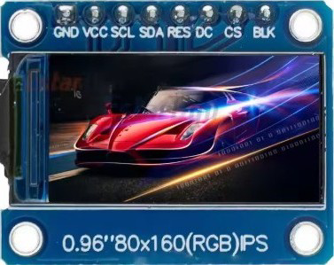
The TFT Display 0.96" is a compact, vibrant thin-film transistor (TFT) display module with a diagonal size of 0.96 inches. It is widely used in embedded systems and microcontroller-based projects for displaying colorful graphics, text, and images. This display is ideal for applications requiring a small form factor and high-quality visuals, such as wearable devices, IoT dashboards, and portable electronics.
Explore Projects Built with TFT Display 0.96"


Explore Projects Built with TFT Display 0.96"
Common Applications
- Wearable devices (e.g., smartwatches, fitness trackers)
- IoT devices and dashboards
- Portable measurement tools
- Small-scale gaming consoles
- Embedded systems requiring graphical user interfaces
Technical Specifications
Below are the key technical details of the TFT Display 0.96":
| Parameter | Value |
|---|---|
| Display Type | TFT (Thin-Film Transistor) |
| Screen Size | 0.96 inches (diagonal) |
| Resolution | 160 x 80 pixels |
| Color Depth | 65K colors (16-bit RGB) |
| Interface | SPI (Serial Peripheral Interface) |
| Operating Voltage | 3.3V (logic level) |
| Backlight Voltage | 3.3V |
| Current Consumption | ~20mA (typical) |
| Driver IC | ST7735 |
| Viewing Angle | ~160° |
| Operating Temperature | -20°C to 70°C |
Pin Configuration
The TFT Display 0.96" typically has an 8-pin interface. Below is the pinout description:
| Pin | Name | Description |
|---|---|---|
| 1 | GND | Ground connection |
| 2 | VCC | Power supply (3.3V) |
| 3 | SCL | Serial Clock Line (SPI clock input) |
| 4 | SDA | Serial Data Line (SPI data input/output) |
| 5 | RES | Reset pin (active low, used to reset the display) |
| 6 | DC | Data/Command pin (high for data, low for command) |
| 7 | CS | Chip Select (active low, used to enable communication with the display module) |
| 8 | BLK | Backlight control (connect to 3.3V for constant backlight or PWM for dimming) |
Usage Instructions
Connecting the TFT Display 0.96" to an Arduino UNO
To use the TFT Display 0.96" with an Arduino UNO, follow these steps:
Wiring the Display: Connect the pins of the display to the Arduino as shown below:
- GND → GND
- VCC → 3.3V
- SCL → Pin 13 (SPI Clock)
- SDA → Pin 11 (SPI MOSI)
- RES → Pin 8
- DC → Pin 9
- CS → Pin 10
- BLK → 3.3V (or a PWM pin for brightness control)
Install Required Libraries: Install the
Adafruit_GFXandAdafruit_ST7735libraries in the Arduino IDE. These libraries provide functions for controlling the display.Upload Example Code: Use the following example code to display text and graphics on the screen:
#include <Adafruit_GFX.h>      // Core graphics library
#include <Adafruit_ST7735.h>   // Library for ST7735 driver

// Define pins for the TFT display
#define TFT_CS   10  // Chip Select pin
#define TFT_RST   8  // Reset pin
#define TFT_DC    9  // Data/Command pin

// Initialize the display object
Adafruit_ST7735 tft = Adafruit_ST7735(TFT_CS, TFT_DC, TFT_RST);

void setup() {
  tft.initR(INITR_BLACKTAB);  // Initialize the display with a specific tab color
  tft.fillScreen(ST77XX_BLACK);  // Clear the screen with black color

  // Display some text
  tft.setTextColor(ST77XX_WHITE);  // Set text color to white
  tft.setTextSize(1);              // Set text size to 1 (smallest)
  tft.setCursor(0, 0);             // Set cursor to top-left corner
  tft.println("Hello, TFT!");      // Print text to the display

  // Draw a red rectangle
  tft.fillRect(10, 20, 50, 30, ST77XX_RED);  // x, y, width, height, color
}

void loop() {
  // Nothing to do here
}
Important Considerations
- Voltage Levels: Ensure the display operates at 3.3V logic levels. If using a 5V microcontroller, use level shifters to avoid damaging the display.
- Backlight Control: For adjustable brightness, connect the BLK pin to a PWM-capable pin on the microcontroller.
- SPI Speed: Use an appropriate SPI clock speed (e.g., 4 MHz) to ensure stable communication.
Troubleshooting and FAQs
Common Issues
Display Not Turning On:
- Check the power connections (VCC and GND).
- Ensure the backlight (BLK) pin is connected to 3.3V or a PWM pin.
No Output on the Screen:
- Verify the SPI connections (SCL, SDA, CS, DC).
- Ensure the
Adafruit_GFXandAdafruit_ST7735libraries are installed correctly. - Check the initialization code for the correct driver and tab color.
Flickering or Unstable Display:
- Reduce the SPI clock speed in the library settings.
- Ensure proper grounding between the display and the microcontroller.
Incorrect Colors or Artifacts:
- Verify the wiring of the DC and CS pins.
- Ensure the display is initialized with the correct tab color (e.g.,
INITR_BLACKTAB).
FAQs
Q: Can I use this display with a 5V microcontroller?
A: Yes, but you must use level shifters to convert the 5V logic signals to 3.3V to avoid damaging the display.
Q: How do I display images on the screen?
A: Use the Adafruit_GFX library's drawBitmap() function or convert images to a compatible format using tools like LCD Image Converter.
Q: Can I control the backlight brightness?
A: Yes, connect the BLK pin to a PWM-capable pin on your microcontroller and use PWM to adjust brightness.
Q: Is this display compatible with other microcontrollers?
A: Yes, it can be used with other microcontrollers like ESP32, STM32, or Raspberry Pi, provided they support SPI communication.