How to Use Low Power 9 Axis MEMS Motion Tracking Device Sensor: Examples, Pinouts, and Specs
Introduction
The ICM-20948 is a compact, low-power 9-axis MEMS motion tracking device manufactured by Generic. It integrates a 3-axis accelerometer, a 3-axis gyroscope, and a 3-axis magnetometer into a single package, enabling precise motion and orientation tracking in three-dimensional space. This sensor is widely used in applications such as robotics, smartphones, wearable devices, drones, and gaming controllers.
Its small form factor and low power consumption make it ideal for battery-powered devices, while its high accuracy and versatility ensure reliable performance in dynamic environments.
Explore Projects Built with Low Power 9 Axis MEMS Motion Tracking Device Sensor

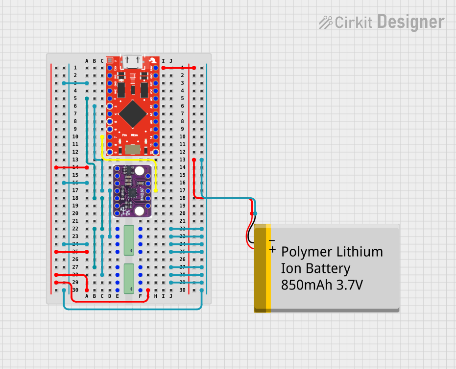
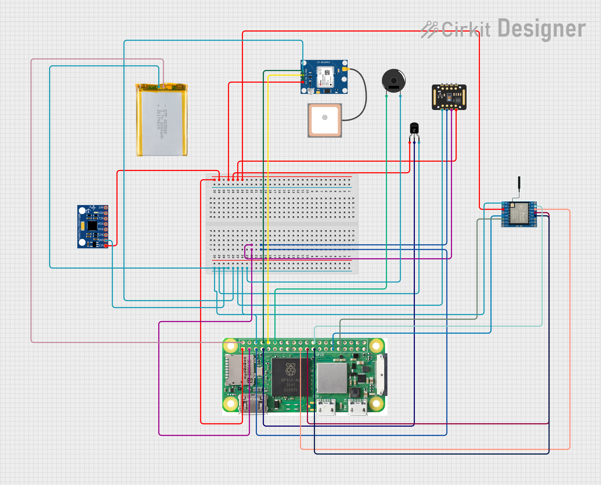
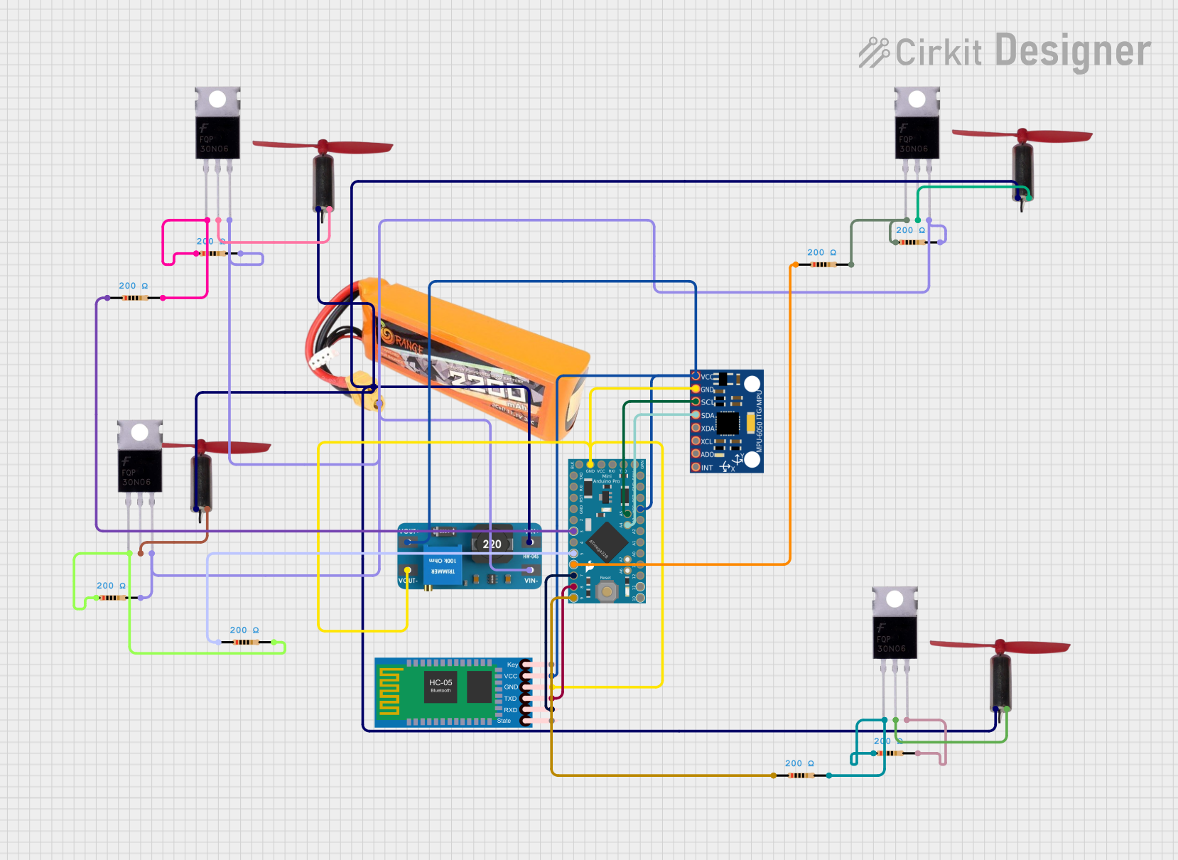
Explore Projects Built with Low Power 9 Axis MEMS Motion Tracking Device Sensor
Technical Specifications
Below are the key technical details of the ICM-20948:
| Parameter | Value |
|---|---|
| Operating Voltage | 1.71V to 3.6V |
| Accelerometer Range | ±2g, ±4g, ±8g, ±16g |
| Gyroscope Range | ±250°/s, ±500°/s, ±1000°/s, ±2000°/s |
| Magnetometer Range | ±4900 µT |
| Communication Interface | I²C (up to 400 kHz) / SPI (up to 7 MHz) |
| Power Consumption | 2.5 mA (typical, full operation) |
| Operating Temperature Range | -40°C to +85°C |
| Package Size | 3 mm x 3 mm x 1 mm |
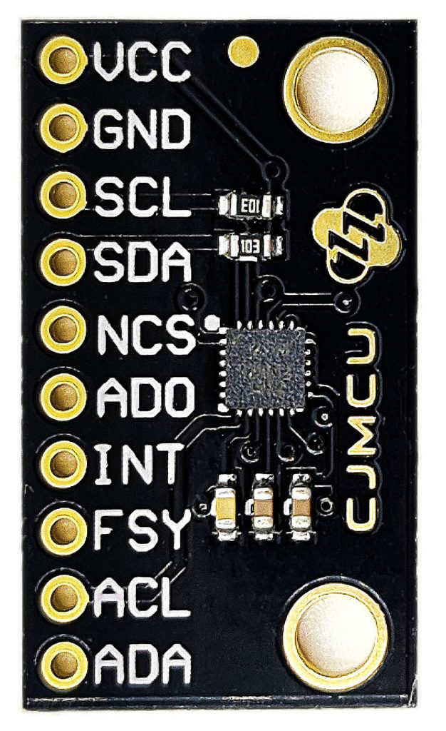
Pin Configuration and Descriptions
The ICM-20948 has 14 pins. Below is the pin configuration and description:
| Pin Number | Pin Name | Description |
|---|---|---|
| 1 | VDD | Power supply input (1.71V to 3.6V). |
| 2 | VDDIO | I/O voltage supply (1.71V to 3.6V). |
| 3 | GND | Ground connection. |
| 4 | SCL/SCLK | I²C clock line / SPI clock line. |
| 5 | SDA/SDI | I²C data line / SPI data input. |
| 6 | SDO/ADO | SPI data output / I²C address selection. |
| 7 | INT | Interrupt output pin. |
| 8 | FSYNC | Frame synchronization input. |
| 9 | AUX_CL | Auxiliary I²C clock line for external sensors. |
| 10 | AUX_DA | Auxiliary I²C data line for external sensors. |
| 11 | RESV | Reserved. Leave unconnected. |
| 12 | RESV | Reserved. Leave unconnected. |
| 13 | RESV | Reserved. Leave unconnected. |
| 14 | RESV | Reserved. Leave unconnected. |
Usage Instructions
How to Use the ICM-20948 in a Circuit
- Power Supply: Connect the VDD pin to a regulated power source (1.71V to 3.6V) and the GND pin to ground. Ensure the VDDIO pin is also connected to the appropriate I/O voltage level.
- Communication Interface:
- For I²C communication, connect the SCL and SDA pins to the corresponding I²C lines on your microcontroller. Use pull-up resistors (typically 4.7 kΩ) on both lines.
- For SPI communication, connect SCLK, SDI, and SDO to the SPI lines on your microcontroller. Configure the ADO pin to set the I²C address or leave it for SPI mode.
- Interrupts: If needed, connect the INT pin to a GPIO pin on your microcontroller to handle interrupts.
- External Sensors: Use the AUX_CL and AUX_DA pins to connect additional sensors via the auxiliary I²C interface.
Important Considerations and Best Practices
- Bypass Capacitors: Place a 0.1 µF ceramic capacitor close to the VDD pin to stabilize the power supply.
- I²C Address: The I²C address can be configured by setting the ADO pin (0x68 when ADO is low, 0x69 when ADO is high).
- Magnetometer Calibration: Perform a calibration routine to account for hard and soft iron distortions in the environment.
- Orientation: Mount the sensor on a stable surface to minimize vibrations and ensure accurate readings.
Example Code for Arduino UNO
Below is an example of how to interface the ICM-20948 with an Arduino UNO using the I²C protocol:
#include <Wire.h>

// ICM-20948 I2C address (default is 0x68 when ADO is low)
#define ICM20948_ADDR 0x68

// Register addresses
#define WHO_AM_I 0x00
#define PWR_MGMT_1 0x06
#define ACCEL_XOUT_H 0x2D

void setup() {
  Wire.begin(); // Initialize I2C communication
  Serial.begin(9600); // Initialize serial communication for debugging

  // Wake up the ICM-20948
  Wire.beginTransmission(ICM20948_ADDR);
  Wire.write(PWR_MGMT_1); // Power management register
  Wire.write(0x01); // Set clock source
  Wire.endTransmission();

  // Verify communication by reading the WHO_AM_I register
  Wire.beginTransmission(ICM20948_ADDR);
  Wire.write(WHO_AM_I);
  Wire.endTransmission();
  Wire.requestFrom(ICM20948_ADDR, 1);

  if (Wire.available()) {
    byte whoAmI = Wire.read();
    Serial.print("WHO_AM_I: 0x");
    Serial.println(whoAmI, HEX);
  } else {
    Serial.println("Failed to communicate with ICM-20948.");
  }
}

void loop() {
  // Read accelerometer data
  Wire.beginTransmission(ICM20948_ADDR);
  Wire.write(ACCEL_XOUT_H); // Start with the high byte of X-axis acceleration
  Wire.endTransmission();
  Wire.requestFrom(ICM20948_ADDR, 6); // Request 6 bytes (X, Y, Z axes)

  if (Wire.available() == 6) {
    int16_t accelX = (Wire.read() << 8) | Wire.read();
    int16_t accelY = (Wire.read() << 8) | Wire.read();
    int16_t accelZ = (Wire.read() << 8) | Wire.read();

    Serial.print("Accel X: ");
    Serial.print(accelX);
    Serial.print(" | Accel Y: ");
    Serial.print(accelY);
    Serial.print(" | Accel Z: ");
    Serial.println(accelZ);
  }

  delay(500); // Delay for readability
}
Troubleshooting and FAQs
Common Issues
No Communication with the Sensor:
- Ensure the I²C address is correct (0x68 or 0x69 depending on the ADO pin).
- Check the pull-up resistors on the I²C lines.
- Verify the power supply voltage is within the specified range.
Incorrect or No Data:
- Confirm the sensor is properly initialized (e.g., power management settings).
- Check for loose or incorrect wiring connections.
- Perform a calibration routine for the accelerometer, gyroscope, and magnetometer.
High Noise in Readings:
- Ensure the sensor is mounted securely to minimize vibrations.
- Use filtering techniques in software to smooth the data.
FAQs
Q: Can the ICM-20948 operate in SPI mode?
A: Yes, the ICM-20948 supports both I²C and SPI communication protocols. Configure the pins accordingly.
Q: How do I calibrate the magnetometer?
A: Perform a figure-eight motion with the sensor to collect data for hard and soft iron calibration. Use software libraries to process the data.
Q: What is the maximum sampling rate?
A: The ICM-20948 supports a maximum sampling rate of 1 kHz for the accelerometer and gyroscope.
Q: Can I use this sensor with a 5V microcontroller?
A: Yes, but you must use a level shifter or ensure the I/O voltage (VDDIO) matches the microcontroller's logic level.