How to Use Adafruit TCS34725 RGB Color Sensor: Examples, Pinouts, and Specs
Introduction
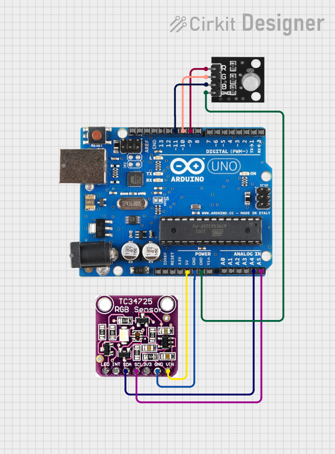
The Adafruit TCS34725 RGB Color Sensor is a sophisticated electronic component designed to detect and measure the color of objects. It employs advanced digital signal processing to accurately determine the RGB (Red, Green, Blue) values and illuminance of the surrounding environment. This sensor is commonly used in applications such as color sorting, ambient light sensing, and color calibration for displays. It interfaces with microcontrollers, such as the Arduino UNO, via the I2C communication protocol.
Explore Projects Built with Adafruit TCS34725 RGB Color Sensor
Explore Projects Built with Adafruit TCS34725 RGB Color Sensor
Technical Specifications
Key Technical Details
- Communication Interface: I2C
- Supply Voltage (VDD): 2.7V to 3.6V
- I/O Voltage (VDDIO): 1.7V to VDD
- Maximum Operating Current: 65 mA
- Operating Temperature Range: -40°C to 85°C
- RGB Color Sensing Range: 380 to 650 nm (with IR filtering)
- Resolution: 16-bit per channel
- Response Time: 2.4 ms (typical)
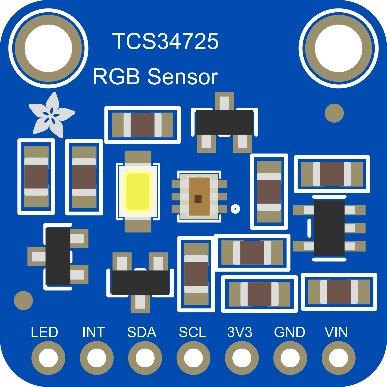
Pin Configuration and Descriptions
| Pin Number | Pin Name | Description |
|---|---|---|
| 1 | VDD | Power supply (2.7V to 3.6V) |
| 2 | GND | Ground |
| 3 | SDA | I2C Data |
| 4 | SCL | I2C Clock |
| 5 | LED | Connect to ground to enable onboard LED |
| 6 | INT | Interrupt output (active low) |
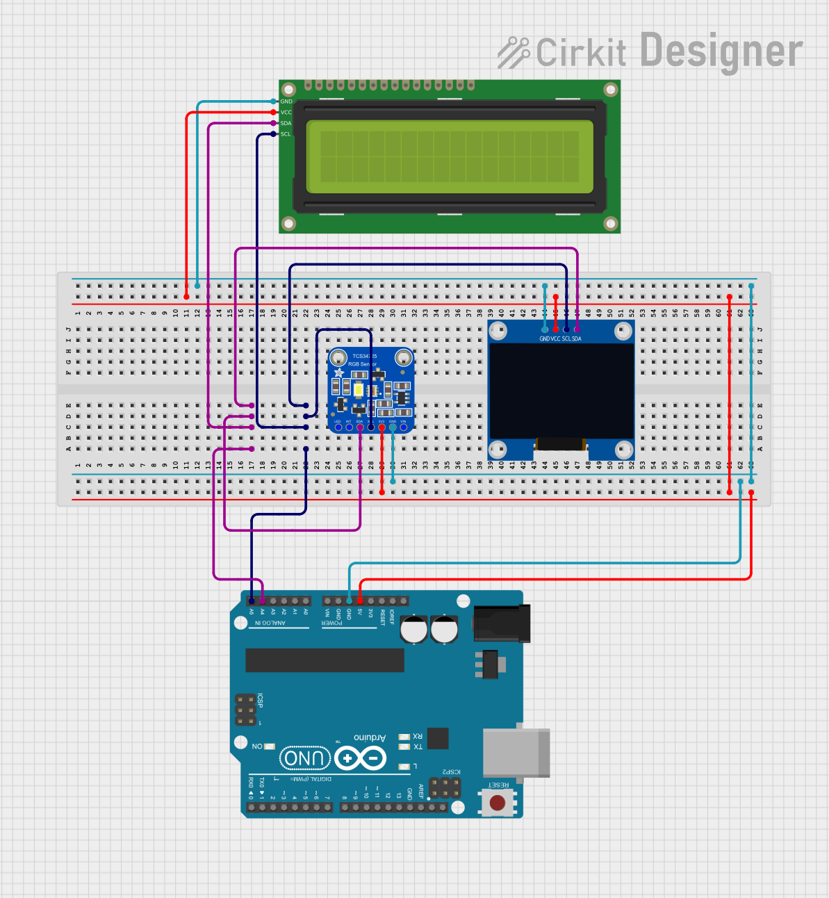
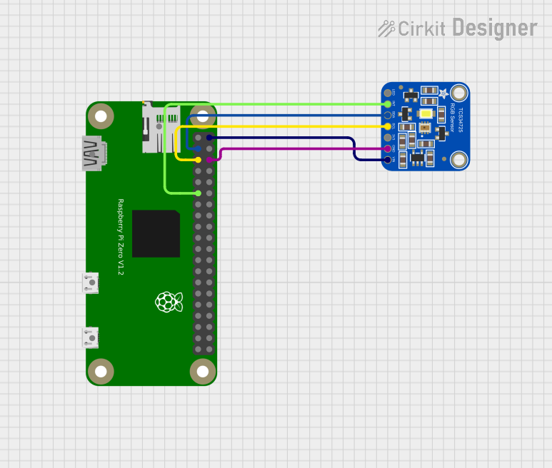
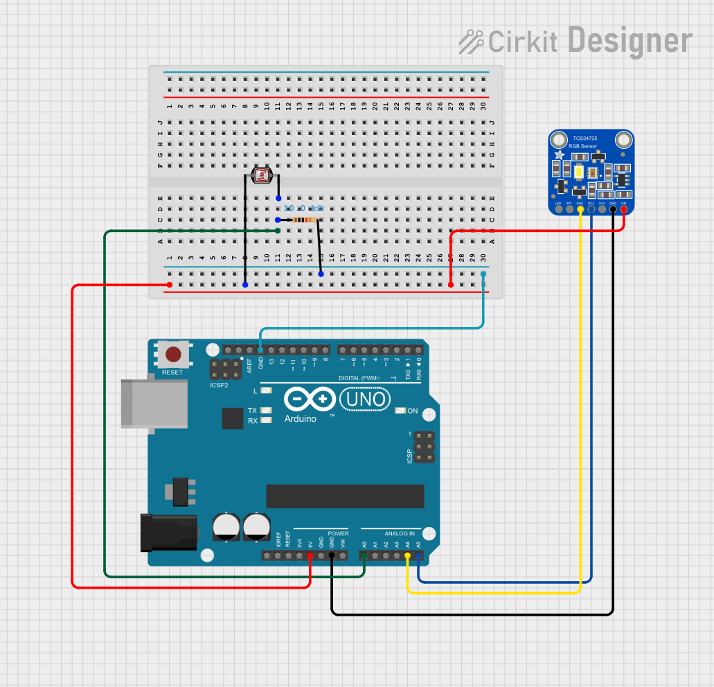
Usage Instructions
Interfacing with a Microcontroller
- Power Connections: Connect the VDD pin to the 3.3V output on your microcontroller and the GND pin to a ground pin.
- I2C Connections: Connect the SDA and SCL pins to the corresponding I2C data and clock lines on your microcontroller.
- LED Control (Optional): If you wish to use the onboard LED for illumination, connect the LED pin to ground.
- Interrupts (Optional): The INT pin can be connected to an external interrupt on your microcontroller if you wish to use the interrupt feature.
Best Practices
- Ensure that the power supply is stable and within the specified voltage range.
- Use pull-up resistors on the I2C data and clock lines if they are not already present on your microcontroller board.
- Avoid exposing the sensor to direct sunlight or strong artificial light sources that could saturate the sensor.
- Calibrate the sensor for the specific lighting conditions of your application to achieve accurate color measurements.
Example Code for Arduino UNO
#include <Wire.h>
#include "Adafruit_TCS34725.h"

// Create an instance of the TCS34725 sensor
Adafruit_TCS34725 tcs = Adafruit_TCS34725(TCS34725_INTEGRATIONTIME_50MS, TCS34725_GAIN_4X);

void setup() {
  Serial.begin(9600);
  if (tcs.begin()) {
    Serial.println("Found sensor");
  } else {
    Serial.println("No TCS34725 sensor found ... check your connections");
    while (1); // halt the program
  }
}

void loop() {
  uint16_t r, g, b, c, colorTemp, lux;

  // Read the color and illuminance from the sensor
  tcs.getRawData(&r, &g, &b, &c);
  colorTemp = tcs.calculateColorTemperature(r, g, b);
  lux = tcs.calculateLux(r, g, b);

  // Print the RGB values and color temperature
  Serial.print("R: "); Serial.print(r);
  Serial.print(" G: "); Serial.print(g);
  Serial.print(" B: "); Serial.print(b);
  Serial.print(" Color Temp: "); Serial.print(colorTemp);
  Serial.print(" Lux: "); Serial.println(lux);

  delay(1000); // Wait for 1 second before the next reading
}
Troubleshooting and FAQs
Common Issues
- Sensor Not Detected: Ensure that the wiring is correct and that the sensor is properly powered. Check the I2C address and the pull-up resistors on the I2C lines.
- Inaccurate Color Readings: Calibrate the sensor for the lighting conditions. Avoid placing the sensor near highly reflective surfaces that could affect the readings.
- LED Not Illuminating: Verify that the LED pin is connected to ground if you wish to use the onboard LED.
FAQs
Q: Can the TCS34725 sensor measure infrared light? A: No, the TCS34725 is designed with an IR filter to measure visible light only.
Q: What is the I2C address of the TCS34725 sensor? A: The default I2C address is 0x29.
Q: How can I change the integration time and gain of the sensor?
A: You can adjust these settings using the Adafruit_TCS34725 library functions setIntegrationTime() and setGain().
Q: Can the sensor operate at 5V? A: The sensor is designed for a supply voltage of 2.7V to 3.6V. Using a 5V supply could damage the sensor.
For further assistance, consult the Adafruit TCS34725 datasheet and the Adafruit support forums.