How to Use KY-011: Examples, Pinouts, and Specs
Introduction
The KY-011 is a small infrared (IR) receiver module designed to receive IR signals from remote controls. It operates at a frequency of 38 kHz, which is the standard frequency for most consumer remote control devices. This module is widely used in projects involving wireless communication, such as remote-controlled robots, home automation systems, and other applications where receiving commands from an IR remote is required.
Explore Projects Built with KY-011


Explore Projects Built with KY-011
Common Applications
- Remote-controlled robots and vehicles
- Home automation systems
- Wireless communication between devices
- TV, DVD, and other consumer electronics control
- Learning and decoding IR remote signals
Technical Specifications
The KY-011 IR receiver module is compact and easy to integrate into various projects. Below are its key technical details:
| Parameter | Value |
|---|---|
| Operating Voltage | 3.3V to 5V |
| Operating Current | 0.4 mA to 1.5 mA |
| Carrier Frequency | 38 kHz |
| Reception Distance | Up to 10 meters (line of sight) |
| Output Signal | Digital (active low) |
| Dimensions | 7.8mm x 5.8mm x 3.1mm |
Pin Configuration
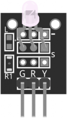
The KY-011 module has three pins, which are typically labeled on the module itself. Below is the pinout description:
| Pin | Name | Description |
|---|---|---|
| 1 | Signal | Digital output pin that sends the received IR signal |
| 2 | VCC | Power supply pin (3.3V to 5V) |
| 3 | GND | Ground pin |
Usage Instructions
The KY-011 IR receiver module is straightforward to use in a circuit. Follow the steps below to integrate it into your project:
Connecting the KY-011
- Power the Module: Connect the
VCCpin to a 3.3V or 5V power source and theGNDpin to the ground of your circuit. - Signal Output: Connect the
Signalpin to a digital input pin on your microcontroller (e.g., Arduino UNO). - Add a Resistor (Optional): For better stability, you can add a pull-up resistor (e.g., 10kΩ) between the
Signalpin andVCC.
Example Circuit with Arduino UNO
Below is an example of how to connect the KY-011 to an Arduino UNO:
- KY-011 Pin 1 (Signal) → Arduino Digital Pin 2
- KY-011 Pin 2 (VCC) → Arduino 5V
- KY-011 Pin 3 (GND) → Arduino GND
Sample Arduino Code
The following Arduino code demonstrates how to use the KY-011 to receive IR signals and print the decoded values to the Serial Monitor. This example uses the IRremote library, which must be installed in your Arduino IDE.
#include <IRremote.h> // Include the IRremote library

const int RECV_PIN = 2; // Define the pin connected to the KY-011 Signal pin
IRrecv irrecv(RECV_PIN); // Create an IR receiver object
decode_results results;  // Variable to store decoded IR data

void setup() {
  Serial.begin(9600); // Initialize serial communication
  irrecv.enableIRIn(); // Start the IR receiver
  Serial.println("KY-011 IR Receiver Ready");
}

void loop() {
  if (irrecv.decode(&results)) { // Check if an IR signal is received
    Serial.print("IR Code Received: ");
    Serial.println(results.value, HEX); // Print the received code in HEX format
    irrecv.resume(); // Prepare to receive the next signal
  }
}
Important Considerations
- Ensure the KY-011 module has a clear line of sight to the IR remote for optimal performance.
- Avoid exposing the module to direct sunlight or strong ambient light, as this can interfere with IR signal reception.
- Use a decoupling capacitor (e.g., 10µF) between
VCCandGNDto reduce noise in the power supply.
Troubleshooting and FAQs
Common Issues and Solutions
No Signal Detected
- Cause: The IR remote is not compatible or the module is not properly connected.
- Solution: Verify the remote operates at 38 kHz and check all connections.
Unstable or Intermittent Signal
- Cause: Electrical noise or insufficient power supply.
- Solution: Add a decoupling capacitor between
VCCandGNDand ensure a stable power source.
Short Reception Range
- Cause: Obstructions or weak IR signal from the remote.
- Solution: Ensure a clear line of sight and replace the remote's batteries if necessary.
Incorrect Decoded Values
- Cause: Incorrect library or improper configuration.
- Solution: Ensure the
IRremotelibrary is installed and the correct pin is defined in the code.
FAQs
Q: Can the KY-011 receive signals from any IR remote?
A: The KY-011 is compatible with most IR remotes operating at 38 kHz, which is the standard frequency for consumer electronics.
Q: Can I use the KY-011 with a 3.3V microcontroller?
A: Yes, the KY-011 operates at both 3.3V and 5V, making it compatible with a wide range of microcontrollers.
Q: How do I increase the reception range?
A: Ensure the module has a clear line of sight to the remote and avoid interference from ambient light sources.
Q: Can the KY-011 send IR signals?
A: No, the KY-011 is an IR receiver module and cannot transmit IR signals. For transmission, use an IR LED module.
By following this documentation, you can effectively integrate the KY-011 IR receiver module into your projects and troubleshoot common issues.