
How to Use Servo SG90: Examples, Pinouts, and Specs

 Design with Servo SG90 in Cirkit Designer
Introduction
The SG90 is a small, lightweight servo motor commonly used in robotics and hobby projects. It provides precise control of angular position and is capable of rotating approximately 180 degrees. The SG90 operates on a 4.8 to 6.0V power supply and is known for its ease of use and affordability.
Explore Projects Built with Servo SG90
 Open Project in Cirkit Designer
 Open Project in Cirkit Designer
 Open Project in Cirkit Designer
 Open Project in Cirkit Designer
Explore Projects Built with Servo SG90
Open Project in Cirkit DesignerOpen Project in Cirkit DesignerOpen Project in Cirkit DesignerOpen Project in Cirkit DesignerCommon Applications
- Robotic arms and grippers
- RC vehicles (cars, boats, planes)
- Automated mechanisms (e.g., door openers, pan-tilt camera mounts)
- Educational and DIY electronics projects
Technical Specifications
Key Specifications
| Parameter | Value |
|---|---|
| Operating Voltage | 4.8V to 6.0V |
| Stall Torque | 1.8 kg·cm (4.8V) |
| Operating Speed | 0.1 s/60° (4.8V) |
| Rotation Angle | 0° to ~180° |
| Weight | 9g |
| Dimensions | 22.2 x 11.8 x 31 mm |
| Control Signal | PWM (Pulse Width Modulation) |
| Connector Type | 3-pin female header |
Pin Configuration
The SG90 servo motor has a 3-pin connector with the following pinout:
| Pin Number | Wire Color | Function |
|---|---|---|
| 1 | Brown | Ground (GND) |
| 2 | Red | Power (VCC) |
| 3 | Orange | Signal (PWM Input) |
Usage Instructions
How to Use the SG90 in a Circuit
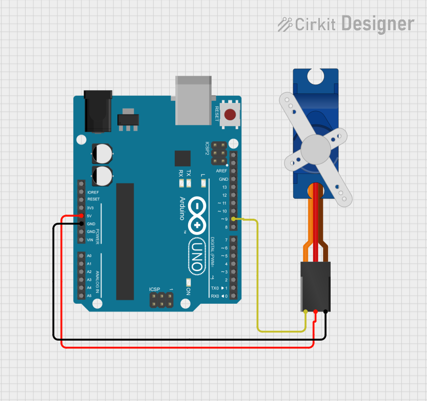
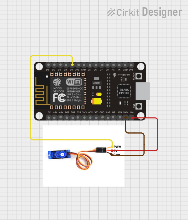
- Power Connection: Connect the red wire to a 5V power source and the brown wire to ground (GND). Ensure the power supply can provide sufficient current (typically 500mA or more).
- Signal Connection: Connect the orange wire to a PWM-capable pin on your microcontroller (e.g., Arduino).
- PWM Signal: The servo position is controlled by the width of the PWM signal:
- A 1ms pulse corresponds to 0°.
- A 1.5ms pulse corresponds to 90° (center position).
- A 2ms pulse corresponds to 180°.
Important Considerations
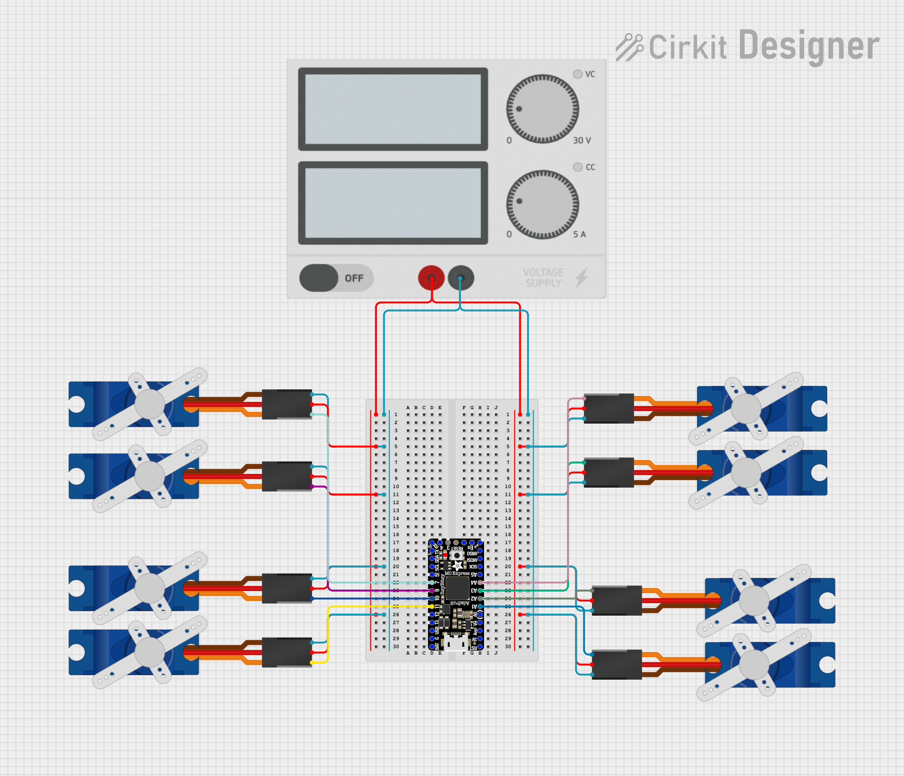
- Power Supply: Avoid powering the servo directly from the Arduino's 5V pin if multiple servos are used, as this may exceed the current capacity of the Arduino's regulator. Use an external power source if needed.
- Signal Stability: Ensure the PWM signal is stable to avoid jittery or erratic servo movement.
- Mechanical Limits: Do not force the servo beyond its physical rotation limits (~180°), as this may damage the internal gears.
Example Code for Arduino UNO
Below is an example of how to control the SG90 servo using an Arduino UNO:
#include <Servo.h> // Include the Servo library

Servo myServo; // Create a Servo object to control the SG90

void setup() {
  myServo.attach(9); // Attach the servo to pin 9 on the Arduino
}

void loop() {
  myServo.write(0); // Move the servo to 0 degrees
  delay(1000); // Wait for 1 second

  myServo.write(90); // Move the servo to 90 degrees (center position)
  delay(1000); // Wait for 1 second

  myServo.write(180); // Move the servo to 180 degrees
  delay(1000); // Wait for 1 second
}
Best Practices
- Use a decoupling capacitor (e.g., 100µF) across the power supply to reduce noise.
- Avoid sudden, large position changes to minimize wear on the servo gears.
- Test the servo with no load before attaching it to a mechanical system.
Troubleshooting and FAQs
Common Issues and Solutions
| Issue | Possible Cause | Solution |
|---|---|---|
| Servo does not move | Incorrect wiring or no power | Verify connections and power supply. |
| Servo jitters or moves erratically | Unstable PWM signal or insufficient power | Use a stable power source and check the signal. |
| Servo overheats | Overloaded or forced beyond limits | Reduce load and ensure proper usage. |
| Limited rotation range | PWM signal out of range | Ensure PWM signal is between 1ms and 2ms. |
FAQs
Q: Can I use the SG90 with a 3.3V microcontroller?
A: Yes, the SG90 can accept a 3.3V PWM signal, but the power supply for the servo itself must still be between 4.8V and 6.0V.
Q: How many SG90 servos can I control with an Arduino?
A: The number depends on the available PWM pins and the power supply capacity. For example, the Arduino UNO has 6 PWM pins.
Q: Can the SG90 rotate continuously?
A: No, the SG90 is a positional servo with a rotation range of approximately 180°. For continuous rotation, use a continuous rotation servo.
Q: Why is my servo making noise but not moving?
A: This could indicate that the servo is overloaded or receiving an incorrect PWM signal. Check the load and signal parameters.
By following this documentation, you can effectively integrate the SG90 servo motor into your projects and troubleshoot common issues.