
How to Use LTC3105: Examples, Pinouts, and Specs
 Design with LTC3105 in Cirkit Designer
Introduction
The LTC3105 is a highly efficient step-up DC-DC converter manufactured by Linear Technology. It is specifically designed for energy harvesting applications, enabling the conversion of low input voltages from sources such as thermoelectric generators (TEGs) or solar cells into higher, regulated output voltages. This makes the LTC3105 ideal for powering low-power devices in remote or energy-constrained environments.
Explore Projects Built with LTC3105
 Open Project in Cirkit Designer
 Open Project in Cirkit Designer
 Open Project in Cirkit Designer
 Open Project in Cirkit Designer
Explore Projects Built with LTC3105
Open Project in Cirkit DesignerOpen Project in Cirkit DesignerOpen Project in Cirkit DesignerOpen Project in Cirkit DesignerCommon Applications and Use Cases
- Energy harvesting from solar panels or thermoelectric generators
- Wireless sensor networks
- Low-power IoT devices
- Battery-free systems
- Remote monitoring equipment
Technical Specifications
The following table outlines the key technical specifications of the LTC3105:
| Parameter | Value |
|---|---|
| Input Voltage Range | 0.225V to 5V |
| Output Voltage Range | 1.4V to 5.25V (programmable via external resistors) |
| Maximum Output Current | Up to 100mA (depending on input voltage and efficiency) |
| Efficiency | Up to 94% |
| Quiescent Current | 22µA (typical) |
| Switching Frequency | 250kHz to 400kHz |
| Integrated MPPT | Yes (Maximum Power Point Tracking for solar and TEG applications) |
| Package | 10-lead DFN (3mm × 3mm) or MSOP |
Pin Configuration and Descriptions
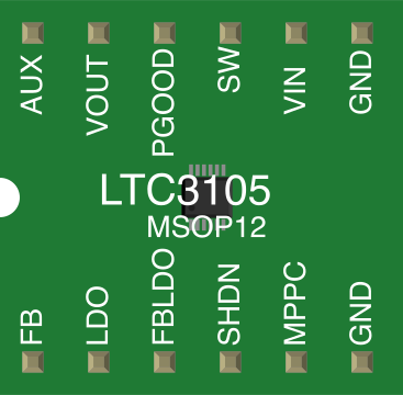
The LTC3105 is available in a 10-lead DFN or MSOP package. The pin configuration is as follows:
| Pin Number | Pin Name | Description |
|---|---|---|
| 1 | VOUT | Regulated output voltage. Connect to the load and output capacitor. |
| 2 | FB | Feedback pin for setting the output voltage. Connect to a resistor divider. |
| 3 | GND | Ground connection. |
| 4 | MPPC | Maximum Power Point Control input. Connect to a resistor divider for MPPT. |
| 5 | SHDN | Shutdown pin. Pull low to disable the converter. |
| 6 | VIN | Input voltage. Connect to the energy source (e.g., solar cell, TEG). |
| 7 | SW | Switching node. Connect to the inductor. |
| 8 | VSTORE | Storage capacitor connection for energy storage. |
| 9 | VCC | Internal supply voltage. Connect a bypass capacitor to ground. |
| 10 | PGD | Power Good indicator. Open-drain output that signals when VOUT is in regulation. |
Usage Instructions
How to Use the LTC3105 in a Circuit
- Input Source Connection: Connect the input voltage source (e.g., solar panel or TEG) to the
VINpin. Ensure the input voltage is within the range of 0.225V to 5V. - Inductor Selection: Choose an appropriate inductor value (typically 10µH to 22µH) and connect it between the
SWpin and the input voltage source. - Output Voltage Configuration: Use a resistor divider network connected to the
FBpin to set the desired output voltage. The formula for the output voltage is: [ V_{OUT} = 1.2V \times \left(1 + \frac{R1}{R2}\right) ] where ( R1 ) and ( R2 ) are the resistors in the divider. - Output Capacitor: Connect a low-ESR capacitor (e.g., 10µF) to the
VOUTpin to stabilize the output voltage. - MPPT Configuration: For energy harvesting applications, connect a resistor divider to the
MPPCpin to set the maximum power point of the input source. - Shutdown Control: Use the
SHDNpin to enable or disable the converter. Pull the pin high to enable and low to disable. - Power Good Monitoring: Use the
PGDpin to monitor the output voltage status. This pin is open-drain and requires a pull-up resistor.
Important Considerations and Best Practices
- Thermal Management: Ensure proper thermal dissipation, especially when operating at higher currents.
- Input Source Impedance: Minimize the impedance of the input source to improve efficiency and stability.
- PCB Layout: Use a compact layout with short traces for the inductor, capacitors, and feedback resistors to reduce noise and improve performance.
- Startup Behavior: The LTC3105 includes an internal startup circuit to operate from very low input voltages. Ensure the input source can provide sufficient power during startup.
Example: Using the LTC3105 with an Arduino UNO
The LTC3105 can be used to power an Arduino UNO from a low-voltage energy source. Below is an example circuit and Arduino code to monitor the PGD pin:
Circuit Connections
- Connect the output of the LTC3105 (
VOUT) to the Arduino'sVINpin. - Connect the
PGDpin of the LTC3105 to a digital input pin on the Arduino (e.g.,D2). - Use a pull-up resistor (e.g., 10kΩ) on the
PGDpin.
Arduino Code
// Define the pin connected to the PGD (Power Good) signal
const int pgdPin = 2;

void setup() {
  // Initialize the serial monitor
  Serial.begin(9600);

  // Configure the PGD pin as an input
  pinMode(pgdPin, INPUT);

  // Print a startup message
  Serial.println("LTC3105 Power Good Monitoring Started");
}

void loop() {
  // Read the state of the PGD pin
  int pgdState = digitalRead(pgdPin);

  // Check if the output voltage is in regulation
  if (pgdState == HIGH) {
    Serial.println("Output voltage is in regulation.");
  } else {
    Serial.println("Output voltage is NOT in regulation.");
  }

  // Wait for 1 second before checking again
  delay(1000);
}
Troubleshooting and FAQs
Common Issues and Solutions
Output Voltage Not Reaching Desired Level
- Cause: Incorrect resistor divider values on the
FBpin. - Solution: Verify the resistor values and recalculate using the output voltage formula.
- Cause: Incorrect resistor divider values on the
Low Efficiency
- Cause: Poor inductor selection or high input source impedance.
- Solution: Use a low-ESR inductor with the recommended value and minimize input source impedance.
Converter Not Starting
- Cause: Insufficient input power or incorrect connections.
- Solution: Ensure the input source can provide enough power during startup and check all connections.
PGD Pin Not Functioning
- Cause: Missing pull-up resistor or incorrect pin configuration.
- Solution: Add a pull-up resistor to the
PGDpin and verify the Arduino code.
FAQs
Q: Can the LTC3105 operate without an MPPT configuration?
A: Yes, the MPPT feature is optional. If not used, connect the MPPC pin to ground.
Q: What is the maximum output current of the LTC3105?
A: The maximum output current depends on the input voltage and efficiency but is typically up to 100mA.
Q: Can the LTC3105 charge a battery?
A: Yes, the LTC3105 can be used to charge small batteries or supercapacitors by connecting them to the VOUT pin.
Q: Is the LTC3105 suitable for powering high-current devices?
A: No, the LTC3105 is designed for low-power applications with a maximum output current of approximately 100mA.