Cirkit Designer
Your all-in-one circuit design IDE
Home /
Component Documentation
How to Use arduino: Examples, Pinouts, and Specs
Introduction
- Arduino is an open-source electronics platform designed for ease of use in both hardware and software. It is widely used for prototyping and developing interactive electronic projects.
- Arduino boards can read inputs from various sensors (e.g., temperature, light, motion) and control outputs such as LEDs, motors, and other actuators.
- Common applications include home automation, robotics, IoT (Internet of Things) devices, and educational projects.
Explore Projects Built with arduino
Arduino Mega 2560-Based Battery-Powered Robotic Car with Ultrasonic and IR Sensors
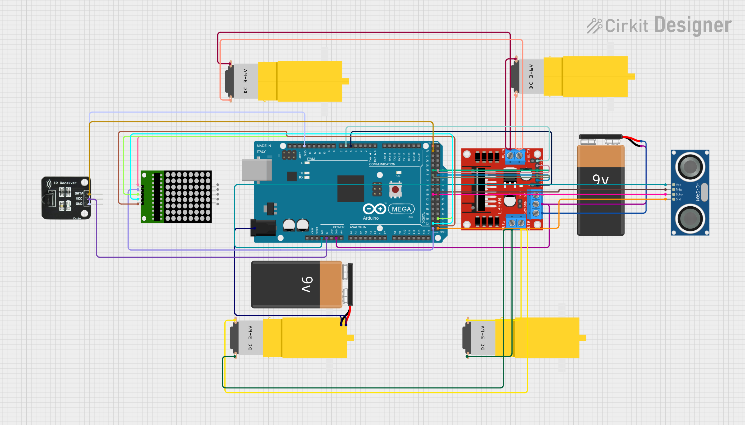
This circuit is a robotic system controlled by an Arduino Mega 2560, which interfaces with an L298N motor driver to control four DC motors. It also includes an HC-SR04 ultrasonic sensor for distance measurement, an IR receiver for remote control, and an 8x8 LED matrix for visual feedback.
Arduino Mega 2560-Based Autonomous Robot with GPS, Bluetooth, and Environmental Sensors
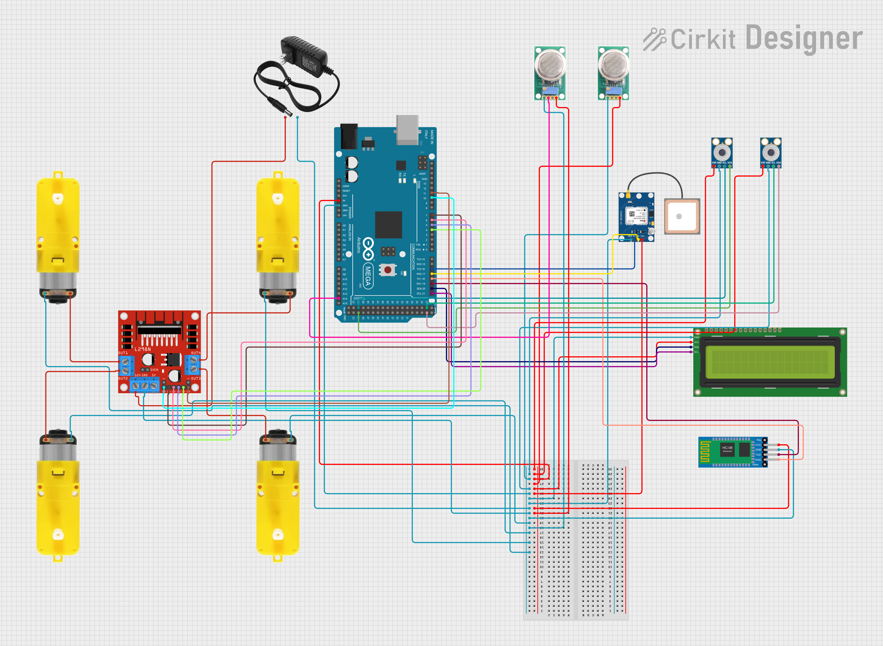
This circuit is a robotic system controlled by an Arduino Mega 2560, which uses multiple sensors including temperature sensors (MLX90614), gas sensors (MQ-136), a GPS module, and a Bluetooth module to navigate and detect environmental conditions. The system drives motors via an L298N motor driver and displays information on a 16x2 I2C LCD, with the ability to receive commands via Bluetooth.
Arduino Mega 2560 Controlled Robotic Arm and Vehicle with Bluetooth Interface
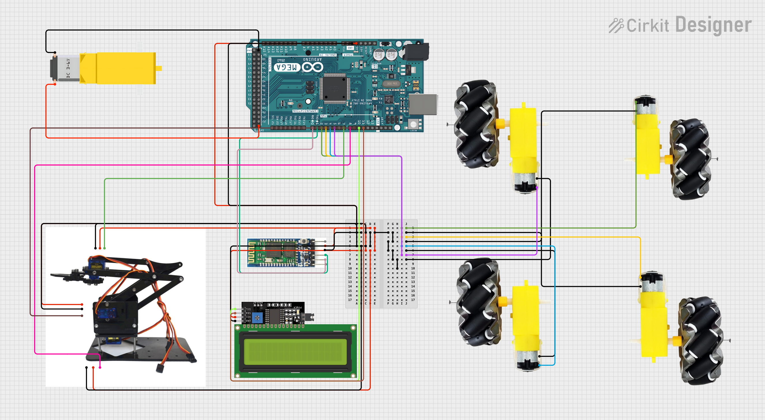
This circuit is designed to control a robotic system with mobility and manipulative capabilities. It uses an Arduino Mega 2560 to drive multiple motors and wheels for movement, a Bluetooth module for wireless communication, and an acrylic robotic arm kit with servos for manipulation. The system also includes an LCD display for user feedback, and the Arduino is programmed to interpret Bluetooth commands to control the motors, servos, and display information.
Arduino UNO-Based Bluetooth-Controlled Robotic Vehicle with Ultrasonic and IR Sensors
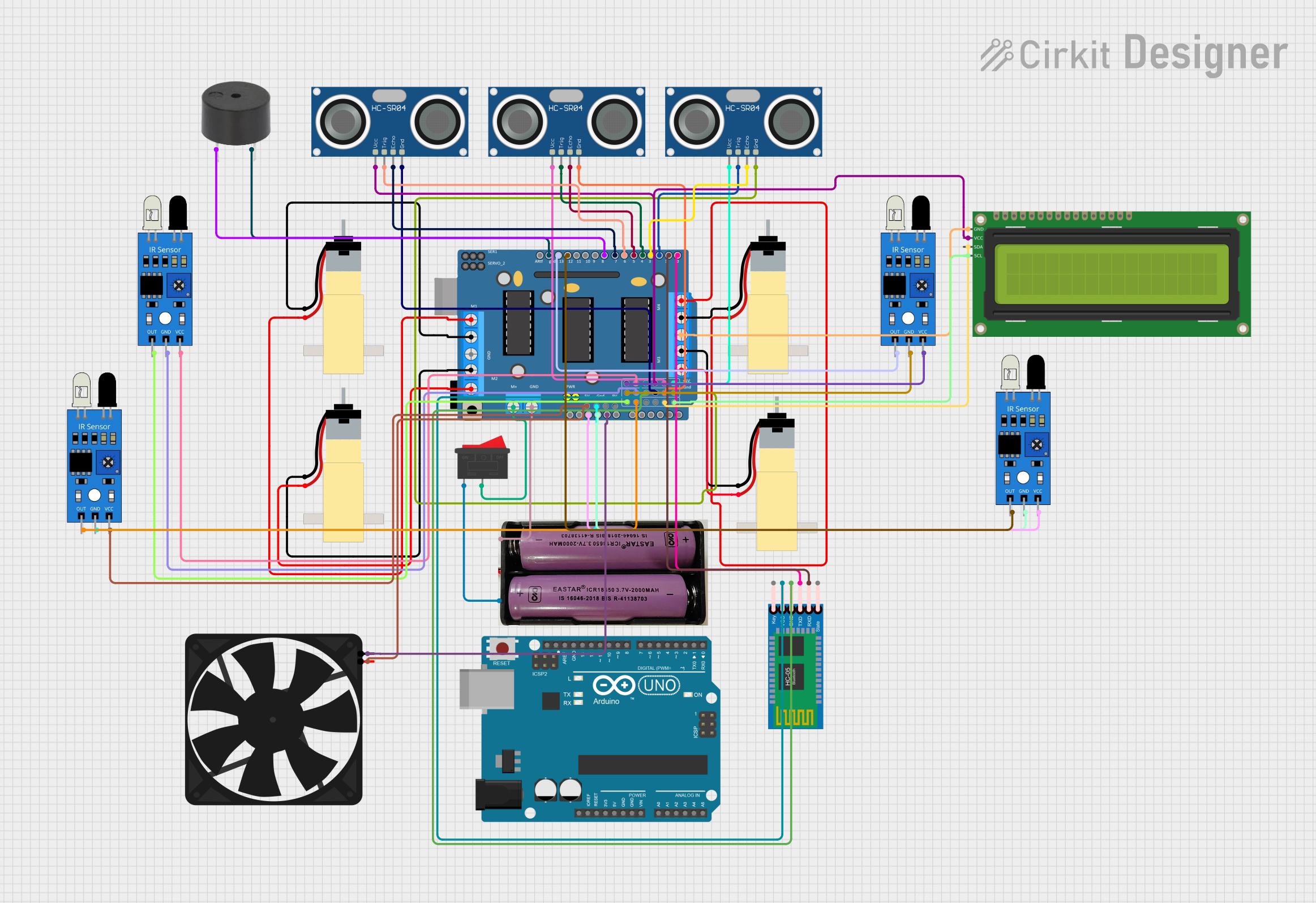
This circuit is a robotic system controlled by an Arduino UNO, featuring four gear motors driven by an L293D driver shield, and equipped with multiple sensors including ultrasonic, IR, and a Bluetooth module for remote communication. The system also includes a fan, buzzer, and an LCD display for user interaction and feedback.
Explore Projects Built with arduino
Arduino Mega 2560-Based Battery-Powered Robotic Car with Ultrasonic and IR Sensors
This circuit is a robotic system controlled by an Arduino Mega 2560, which interfaces with an L298N motor driver to control four DC motors. It also includes an HC-SR04 ultrasonic sensor for distance measurement, an IR receiver for remote control, and an 8x8 LED matrix for visual feedback.
Arduino Mega 2560-Based Autonomous Robot with GPS, Bluetooth, and Environmental Sensors
This circuit is a robotic system controlled by an Arduino Mega 2560, which uses multiple sensors including temperature sensors (MLX90614), gas sensors (MQ-136), a GPS module, and a Bluetooth module to navigate and detect environmental conditions. The system drives motors via an L298N motor driver and displays information on a 16x2 I2C LCD, with the ability to receive commands via Bluetooth.
Arduino Mega 2560 Controlled Robotic Arm and Vehicle with Bluetooth Interface
This circuit is designed to control a robotic system with mobility and manipulative capabilities. It uses an Arduino Mega 2560 to drive multiple motors and wheels for movement, a Bluetooth module for wireless communication, and an acrylic robotic arm kit with servos for manipulation. The system also includes an LCD display for user feedback, and the Arduino is programmed to interpret Bluetooth commands to control the motors, servos, and display information.
Arduino UNO-Based Bluetooth-Controlled Robotic Vehicle with Ultrasonic and IR Sensors
This circuit is a robotic system controlled by an Arduino UNO, featuring four gear motors driven by an L293D driver shield, and equipped with multiple sensors including ultrasonic, IR, and a Bluetooth module for remote communication. The system also includes a fan, buzzer, and an LCD display for user interaction and feedback.
Technical Specifications
Arduino boards come in various models, such as the Arduino UNO, Mega, Nano, and others. Below are the general specifications for the Arduino UNO, one of the most popular models:
Key Technical Details
| Specification | Value |
|---|---|
| Microcontroller | ATmega328P |
| Operating Voltage | 5V |
| Input Voltage (limit) | 6-20V |
| Digital I/O Pins | 14 (6 PWM outputs) |
| Analog Input Pins | 6 |
| DC Current per I/O Pin | 20 mA |
| Flash Memory | 32 KB (0.5 KB used by bootloader) |
| SRAM | 2 KB |
| EEPROM | 1 KB |
| Clock Speed | 16 MHz |
| USB Interface | Type-B USB |
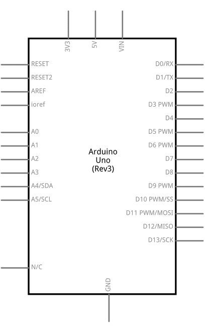
Pin Configuration and Descriptions
| Pin Name | Description |
|---|---|
| Digital Pins | Pins 0-13: Used for digital input/output. Pins 3, 5, 6, 9, 10, and 11 support PWM. |
| Analog Pins | Pins A0-A5: Used for analog input (10-bit resolution). |
| Power Pins | 5V, 3.3V, GND, Vin: Provide power to external components. |
| Reset | Resets the microcontroller. |
| TX/RX | Pins 0 (RX) and 1 (TX): Used for serial communication. |
| ICSP Header | Used for in-circuit serial programming of the microcontroller. |
Usage Instructions
How to Use the Arduino in a Circuit
- Power the Arduino:
- Connect the Arduino to your computer using a USB cable or use an external power supply (6-12V via the barrel jack or Vin pin).
- Connect Sensors and Actuators:
- Use the digital and analog pins to connect sensors (e.g., temperature, light) and actuators (e.g., LEDs, motors).
- Write and Upload Code:
- Use the Arduino IDE to write code in C/C++.
- Upload the code to the Arduino board via the USB connection.
Example: Blinking an LED
Below is an example of how to blink an LED connected to pin 13 of the Arduino UNO:
// This program blinks an LED connected to pin 13 of the Arduino UNO.
// The LED will turn on for 1 second and off for 1 second in a loop.

void setup() {
  pinMode(13, OUTPUT); // Set pin 13 as an output pin
}

void loop() {
  digitalWrite(13, HIGH); // Turn the LED on
  delay(1000);            // Wait for 1 second
  digitalWrite(13, LOW);  // Turn the LED off
  delay(1000);            // Wait for 1 second
}
Important Considerations and Best Practices
- Power Supply: Ensure the power supply voltage is within the recommended range (7-12V for external power).
- Pin Current Limits: Do not exceed 20 mA per I/O pin to avoid damaging the microcontroller.
- Grounding: Always connect the ground (GND) of the Arduino to the ground of external components.
- Code Optimization: Use functions and libraries to keep your code modular and efficient.
Troubleshooting and FAQs
Common Issues and Solutions
Arduino Not Detected by Computer:
- Ensure the USB cable is properly connected.
- Check if the correct COM port is selected in the Arduino IDE.
- Install or update the USB driver for the Arduino board.
Code Upload Fails:
- Verify that the correct board and port are selected in the Arduino IDE.
- Press the reset button on the Arduino before uploading the code.
- Ensure no other program is using the COM port.
Components Not Working as Expected:
- Double-check the wiring and connections.
- Verify that the correct pins are defined in the code.
- Use a multimeter to test the voltage and continuity of the circuit.
FAQs
Q: Can I power the Arduino with batteries?
- A: Yes, you can use a 9V battery connected to the barrel jack or Vin pin.
Q: What is the maximum current the Arduino can supply?
- A: The 5V pin can supply up to 500 mA when powered via USB, and the 3.3V pin can supply up to 50 mA.
Q: Can I use the Arduino to control high-power devices?
- A: Yes, but you will need external components like relays, transistors, or motor drivers to handle high currents or voltages.
By following this documentation, you can effectively use the Arduino platform for a wide range of projects and applications.