Cirkit Designer Logo
Cirkit Designer
Your all-in-one circuit design IDE
Home / 
Component Documentation

How to Use KY-003 Hall Sensor: Examples, Pinouts, and Specs

Image of KY-003 Hall Sensor
Cirkit Designer LogoDesign with KY-003 Hall Sensor in Cirkit Designer

Introduction

The KY-003 Hall Sensor is a compact and versatile device designed to detect the presence of a magnetic field. It operates by outputting a digital signal when a magnetic field is detected, making it an essential component in various applications. The sensor is widely used in position sensing, speed detection, and proximity sensing. Its simplicity and reliability make it a popular choice for hobbyists, students, and professionals working on magnetic field detection projects.

Explore Projects Built with KY-003 Hall Sensor

Use Cirkit Designer to design, explore, and prototype these projects online. Some projects support real-time simulation. Click "Open Project" to start designing instantly!
Arduino Mega 2560 Hall Sensor Interface for Real-Time Magnetic Field Detection
Image of Hall Effect CD: A project utilizing KY-003 Hall Sensor in a practical application
This circuit uses an Arduino Mega 2560 to read data from a Hall Sensor, which is powered through a terminal block connected to the Arduino's 5V supply. The sensor's ground is connected to the Arduino's ground, and its signal output is read by the Arduino on pin D2.
Cirkit Designer LogoOpen Project in Cirkit Designer
Arduino UNO-Based Sensor Monitoring System with IR and Hall Sensors
Image of BIOE4900: A project utilizing KY-003 Hall Sensor in a practical application
This circuit uses an Arduino UNO to interface with an IR sensor and a Hall sensor. The IR sensor's output is connected to digital pin D2, while the Hall sensor's signal pin is connected to analog pin A0. The circuit is designed to read sensor data and potentially control an external device through the wire connector connected to digital pins D5 and D6.
Cirkit Designer LogoOpen Project in Cirkit Designer
Arduino Nano ESP32 Hall Sensor Interface with LCD Display
Image of hall effect + speedometer: A project utilizing KY-003 Hall Sensor in a practical application
This circuit includes a Hall sensor connected to an Arduino Nano ESP32 microcontroller, which is likely used to detect magnetic fields and send the data to the microcontroller on pin D12. The Arduino is also interfaced with an LCD display, with connections for power, ground, control (RS, E), and data (DB4-DB7) to display information. The absence of code suggests that the microcontroller's behavior is not defined in this context, but it is set up to read the Hall sensor and output to the LCD.
Cirkit Designer LogoOpen Project in Cirkit Designer
Arduino UNO-Based Smart Hall Management System with PIR Sensors and Temperature Control
Image of electric: A project utilizing KY-003 Hall Sensor in a practical application
This circuit is a hall monitoring system using an Arduino UNO, which tracks the number of people entering and exiting via PIR sensors, controls a chiller based on temperature readings from a temperature sensor, and activates a buzzer when the hall reaches maximum capacity. The system also periodically publishes data about the hall's temperature, chiller status, and occupancy.
Cirkit Designer LogoOpen Project in Cirkit Designer

Explore Projects Built with KY-003 Hall Sensor

Use Cirkit Designer to design, explore, and prototype these projects online. Some projects support real-time simulation. Click "Open Project" to start designing instantly!
Image of Hall Effect CD: A project utilizing KY-003 Hall Sensor in a practical application
Arduino Mega 2560 Hall Sensor Interface for Real-Time Magnetic Field Detection
This circuit uses an Arduino Mega 2560 to read data from a Hall Sensor, which is powered through a terminal block connected to the Arduino's 5V supply. The sensor's ground is connected to the Arduino's ground, and its signal output is read by the Arduino on pin D2.
Cirkit Designer LogoOpen Project in Cirkit Designer
Image of BIOE4900: A project utilizing KY-003 Hall Sensor in a practical application
Arduino UNO-Based Sensor Monitoring System with IR and Hall Sensors
This circuit uses an Arduino UNO to interface with an IR sensor and a Hall sensor. The IR sensor's output is connected to digital pin D2, while the Hall sensor's signal pin is connected to analog pin A0. The circuit is designed to read sensor data and potentially control an external device through the wire connector connected to digital pins D5 and D6.
Cirkit Designer LogoOpen Project in Cirkit Designer
Image of hall effect + speedometer: A project utilizing KY-003 Hall Sensor in a practical application
Arduino Nano ESP32 Hall Sensor Interface with LCD Display
This circuit includes a Hall sensor connected to an Arduino Nano ESP32 microcontroller, which is likely used to detect magnetic fields and send the data to the microcontroller on pin D12. The Arduino is also interfaced with an LCD display, with connections for power, ground, control (RS, E), and data (DB4-DB7) to display information. The absence of code suggests that the microcontroller's behavior is not defined in this context, but it is set up to read the Hall sensor and output to the LCD.
Cirkit Designer LogoOpen Project in Cirkit Designer
Image of electric: A project utilizing KY-003 Hall Sensor in a practical application
Arduino UNO-Based Smart Hall Management System with PIR Sensors and Temperature Control
This circuit is a hall monitoring system using an Arduino UNO, which tracks the number of people entering and exiting via PIR sensors, controls a chiller based on temperature readings from a temperature sensor, and activates a buzzer when the hall reaches maximum capacity. The system also periodically publishes data about the hall's temperature, chiller status, and occupancy.
Cirkit Designer LogoOpen Project in Cirkit Designer

Technical Specifications

  • Operating Voltage: 3.3V to 5V
  • Output Type: Digital (High/Low)
  • Current Consumption: 4mA (typical)
  • Magnetic Sensitivity: Detects both North and South poles of a magnet
  • Operating Temperature: -40°C to 85°C
  • Dimensions: 18.5mm x 15mm x 7mm (approx.)

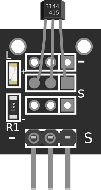
Pin Configuration and Descriptions

The KY-003 Hall Sensor module has three pins, as described in the table below:

Pin Number Pin Name Description
1 Signal Outputs a digital signal (HIGH when a magnetic field is detected, LOW otherwise).
2 VCC Power supply pin (3.3V to 5V).
3 GND Ground connection.

Usage Instructions

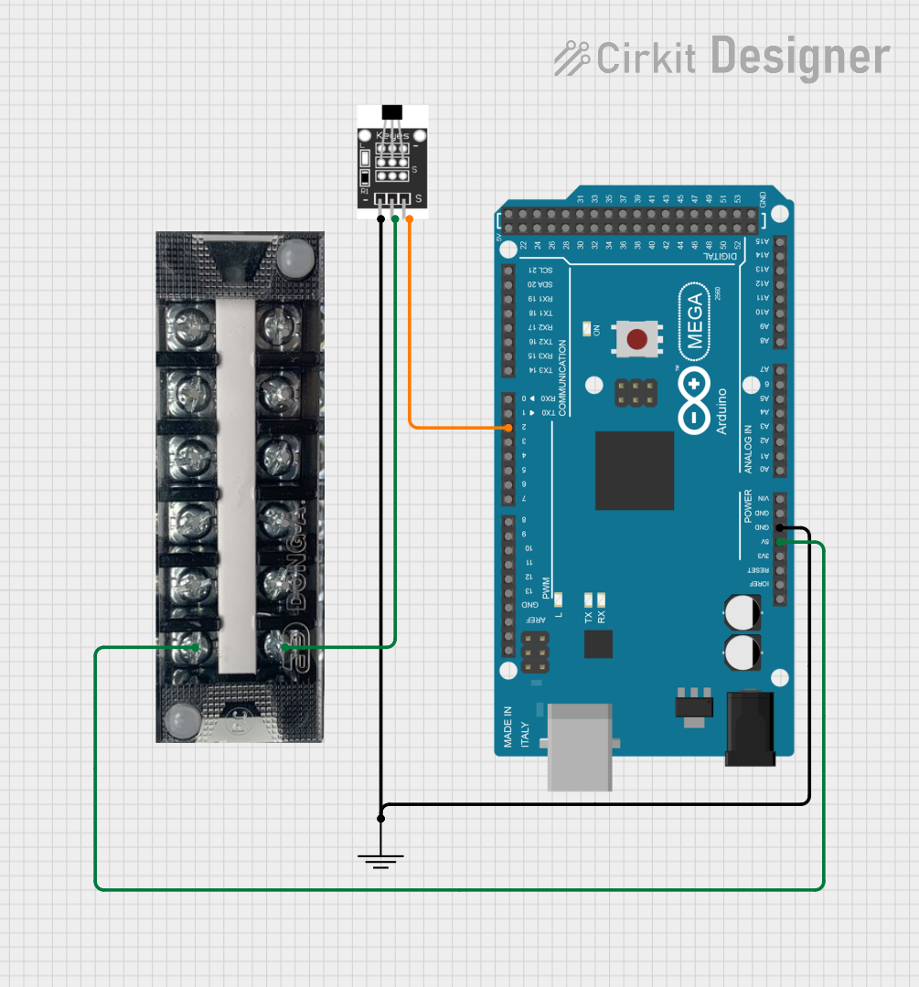
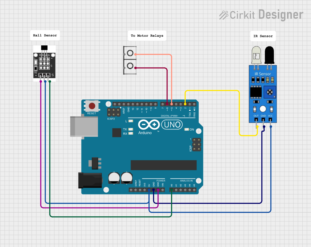
How to Use the KY-003 Hall Sensor in a Circuit

  1. Wiring the Sensor:

    • Connect the VCC pin to a 3.3V or 5V power source.
    • Connect the GND pin to the ground of your circuit.
    • Connect the Signal pin to a digital input pin on your microcontroller (e.g., Arduino).
  2. Magnetic Field Detection:

    • When a magnetic field is detected, the sensor outputs a HIGH signal (logic 1).
    • When no magnetic field is present, the sensor outputs a LOW signal (logic 0).
  3. Example Circuit:

    • Place the KY-003 Hall Sensor near a magnet to test its functionality.
    • Use an LED or a microcontroller to observe the output signal.

Important Considerations and Best Practices

  • Ensure the sensor is powered within its operating voltage range (3.3V to 5V).
  • Avoid exposing the sensor to extreme temperatures or strong electromagnetic interference.
  • For accurate detection, position the sensor perpendicular to the magnetic field.
  • Use pull-down resistors if necessary to stabilize the signal output.

Arduino UNO Example Code

Below is an example code to interface the KY-003 Hall Sensor with an Arduino UNO:

// KY-003 Hall Sensor Example Code for Arduino UNO
// This code reads the digital output of the KY-003 Hall Sensor and turns on an LED
// when a magnetic field is detected.

const int hallSensorPin = 2; // KY-003 Signal pin connected to digital pin 2
const int ledPin = 13;       // Onboard LED pin

void setup() {
  pinMode(hallSensorPin, INPUT); // Set the hall sensor pin as input
  pinMode(ledPin, OUTPUT);       // Set the LED pin as output
  Serial.begin(9600);            // Initialize serial communication for debugging
}

void loop() {
  int sensorState = digitalRead(hallSensorPin); // Read the sensor's output

  if (sensorState == HIGH) {
    // Magnetic field detected
    digitalWrite(ledPin, HIGH); // Turn on the LED
    Serial.println("Magnetic field detected!");
  } else {
    // No magnetic field detected
    digitalWrite(ledPin, LOW);  // Turn off the LED
    Serial.println("No magnetic field.");
  }

  delay(100); // Small delay for stability
}

Troubleshooting and FAQs

Common Issues and Solutions

  1. The sensor does not detect a magnetic field:

    • Ensure the sensor is properly powered (3.3V to 5V).
    • Verify the connections to the microcontroller or circuit.
    • Check if the magnet is strong enough and positioned correctly.
  2. Unstable or fluctuating output:

    • Use a pull-down resistor on the signal pin to stabilize the output.
    • Ensure there is no electromagnetic interference near the sensor.
  3. No output signal:

    • Confirm that the sensor is not damaged.
    • Test the sensor with a different microcontroller or circuit.

FAQs

Q: Can the KY-003 Hall Sensor detect both poles of a magnet?
A: Yes, the KY-003 Hall Sensor can detect both the North and South poles of a magnet.

Q: What is the maximum distance for magnetic field detection?
A: The detection range depends on the strength of the magnet. Typically, the sensor works best within a few centimeters of the magnet.

Q: Can I use the KY-003 Hall Sensor with a 3.3V microcontroller?
A: Yes, the sensor operates within a voltage range of 3.3V to 5V, making it compatible with 3.3V microcontrollers like the ESP32.

Q: Is the KY-003 Hall Sensor suitable for outdoor use?
A: While the sensor can operate in a wide temperature range, it is not waterproof or weatherproof. Use appropriate enclosures for outdoor applications.