How to Use F50-ATS Relais de transfert automatique 120/240Vca: Examples, Pinouts, and Specs
Introduction
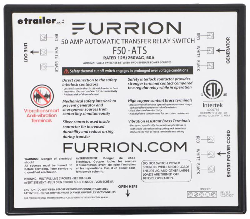
The F50-ATS Automatic Transfer Switch Relay, manufactured by Furion, is a reliable and efficient component designed for switching between two power sources. It is commonly used in backup power systems to ensure a seamless transition between primary and secondary power supplies, such as utility power and a generator. The F50-ATS operates at 120/240V AC and is ideal for maintaining uninterrupted power during outages or power fluctuations.
Explore Projects Built with F50-ATS Relais de transfert automatique 120/240Vca


Explore Projects Built with F50-ATS Relais de transfert automatique 120/240Vca
Common Applications
- Residential and commercial backup power systems
- RV and marine power management
- Industrial equipment requiring dual power source redundancy
- Data centers and critical infrastructure
Technical Specifications
Key Technical Details
| Parameter | Value |
|---|---|
| Operating Voltage | 120/240V AC |
| Frequency | 50/60 Hz |
| Maximum Current Rating | 50 Amps |
| Switching Time | < 30 milliseconds |
| Operating Temperature | -20°C to 60°C (-4°F to 140°F) |
| Dimensions | 10 x 8 x 4 inches |
| Weight | 3.5 lbs (1.6 kg) |
| Certifications | UL Listed, CE Certified |
Pin Configuration and Descriptions
The F50-ATS features terminal blocks for wiring connections. Below is the pin configuration:
| Terminal Label | Description |
|---|---|
| L1 (Input) | Line 1 input from primary power source (utility) |
| L2 (Input) | Line 2 input from primary power source (utility) |
| N (Input) | Neutral input from primary power source |
| GND | Ground connection |
| L1 (Backup) | Line 1 input from secondary power source (generator) |
| L2 (Backup) | Line 2 input from secondary power source (generator) |
| N (Backup) | Neutral input from secondary power source |
| L1 (Output) | Line 1 output to load |
| L2 (Output) | Line 2 output to load |
| N (Output) | Neutral output to load |
Usage Instructions
How to Use the F50-ATS in a Circuit
Power Source Connections:
- Connect the primary power source (e.g., utility power) to the
L1 (Input),L2 (Input), andN (Input)terminals. - Connect the secondary power source (e.g., generator) to the
L1 (Backup),L2 (Backup), andN (Backup)terminals. - Ensure proper grounding by connecting the ground wire to the
GNDterminal.
- Connect the primary power source (e.g., utility power) to the
Load Connections:
- Connect the load (e.g., appliances or equipment) to the
L1 (Output),L2 (Output), andN (Output)terminals.
- Connect the load (e.g., appliances or equipment) to the
Testing the System:
- Power on the primary source and verify that the load is receiving power.
- Simulate a power outage by disconnecting the primary source. The F50-ATS should automatically switch to the secondary source within 30 milliseconds.
- Restore the primary source and verify that the relay switches back seamlessly.
Safety Precautions:
- Always disconnect power before wiring or servicing the F50-ATS.
- Use appropriately rated wires and circuit breakers to prevent overloading.
- Ensure all connections are secure and insulated to avoid short circuits.
Important Considerations
- The F50-ATS is designed for single-phase systems only. Do not use it in three-phase systems.
- Regularly inspect the relay for signs of wear or damage, especially in high-load applications.
- Ensure the generator is properly grounded and configured to match the voltage and frequency requirements of the F50-ATS.
Arduino Integration
While the F50-ATS is not typically controlled by microcontrollers like Arduino, you can monitor its status using an Arduino by connecting sensors to the output terminals. Below is an example code snippet for monitoring the output voltage:
// Example Arduino code to monitor F50-ATS output voltage
const int voltagePin = A0; // Analog pin connected to a voltage divider
float voltage = 0.0;

void setup() {
  Serial.begin(9600); // Initialize serial communication
}

void loop() {
  int sensorValue = analogRead(voltagePin); // Read analog input
  voltage = (sensorValue * 5.0) / 1023.0; // Convert to voltage (assuming 5V ADC)

  // Print the voltage to the Serial Monitor
  Serial.print("Output Voltage: ");
  Serial.print(voltage);
  Serial.println(" V");

  delay(1000); // Wait 1 second before next reading
}
Note: Use a voltage divider circuit to step down the 120/240V AC to a safe level for the Arduino's analog input.
Troubleshooting and FAQs
Common Issues and Solutions
| Issue | Possible Cause | Solution |
|---|---|---|
| Relay does not switch to backup | Backup power source not connected | Verify wiring and ensure generator is operational |
| Load does not receive power | Loose or incorrect wiring | Check all connections and tighten terminals |
| Frequent switching between sources | Voltage fluctuations in primary source | Install a voltage stabilizer or UPS |
| Overheating of the relay | Overloading or poor ventilation | Reduce load or improve airflow around the relay |
FAQs
Can the F50-ATS handle three-phase power?
No, the F50-ATS is designed for single-phase systems only.What is the maximum load capacity of the F50-ATS?
The relay can handle up to 50 Amps at 120/240V AC.Does the F50-ATS require manual intervention during switching?
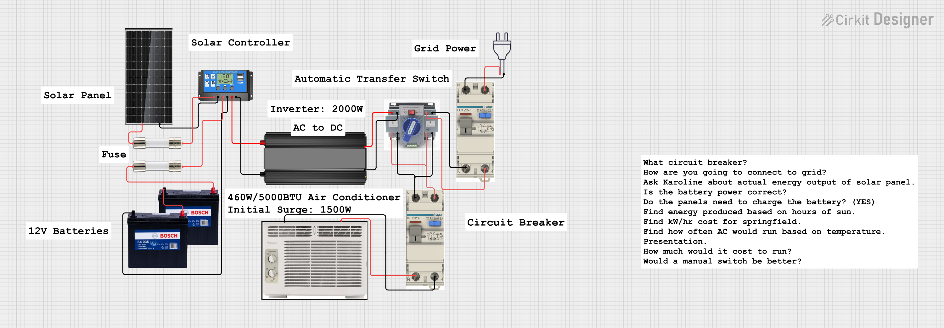
No, the F50-ATS is fully automatic and does not require manual intervention.Can I use the F50-ATS with solar power systems?
Yes, as long as the solar inverter output matches the voltage and frequency requirements of the F50-ATS.
By following this documentation, users can effectively integrate the F50-ATS into their power systems and ensure reliable operation.