
How to Use DC Circuit breaker MCCB: Examples, Pinouts, and Specs
 Design with DC Circuit breaker MCCB in Cirkit Designer
Introduction
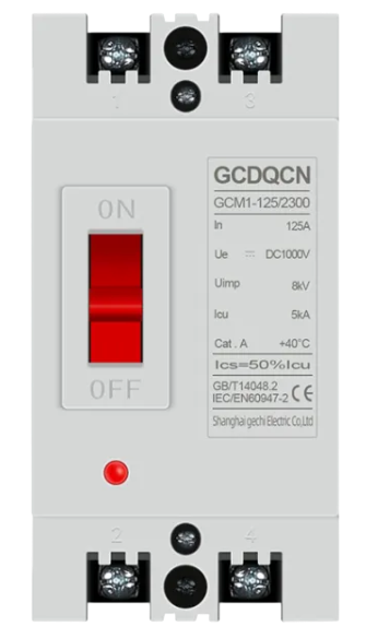
A Molded Case Circuit Breaker (MCCB) designed for direct current (DC) applications is a critical component in electrical systems. It provides overcurrent protection and short-circuit protection, ensuring the safety and reliability of DC circuits. MCCBs are widely used in industrial, commercial, and residential applications where DC power systems are employed.
Explore Projects Built with DC Circuit breaker MCCB
 Open Project in Cirkit Designer
 Open Project in Cirkit Designer
 Open Project in Cirkit Designer
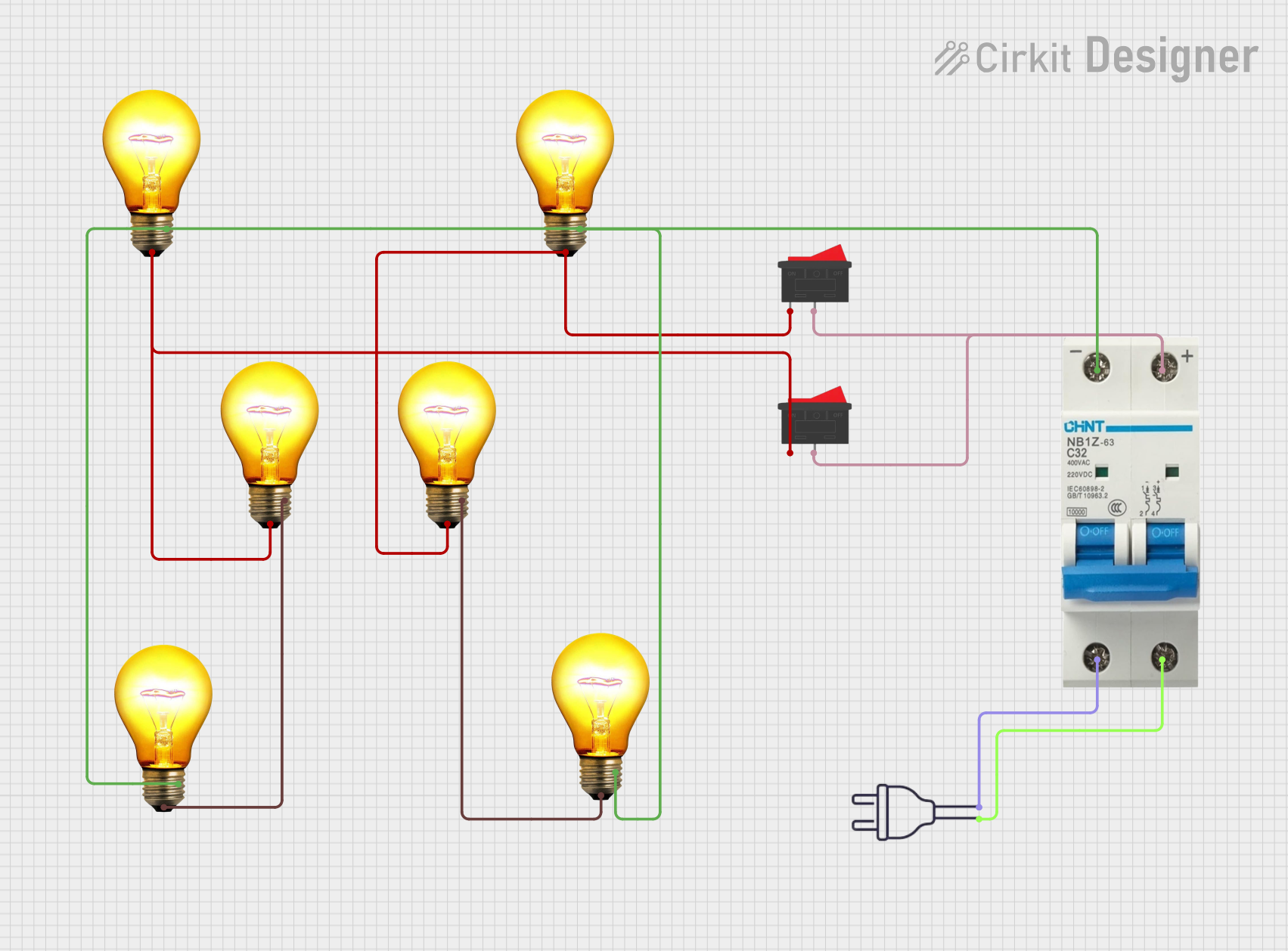 Open Project in Cirkit Designer
Explore Projects Built with DC Circuit breaker MCCB
Open Project in Cirkit DesignerOpen Project in Cirkit DesignerOpen Project in Cirkit DesignerOpen Project in Cirkit DesignerCommon Applications and Use Cases
- Protection of DC power distribution systems in solar energy installations
- Overcurrent protection in battery storage systems
- Short-circuit protection in electric vehicle (EV) charging stations
- Industrial machinery and equipment powered by DC circuits
- Backup power systems and uninterruptible power supplies (UPS)
Technical Specifications
Below are the key technical details of a typical DC Circuit Breaker MCCB:
| Parameter | Specification |
|---|---|
| Rated Voltage | Up to 1000 V DC |
| Rated Current | 10 A to 1600 A (varies by model) |
| Breaking Capacity | 10 kA to 100 kA |
| Number of Poles | 1P, 2P, 3P, or 4P |
| Operating Temperature Range | -25°C to +70°C |
| Mounting Type | DIN rail or panel-mounted |
| Trip Mechanism | Thermal-magnetic or electronic |
| Standards Compliance | IEC 60947-2, UL 489, or equivalent |
Pin Configuration and Descriptions
The MCCB does not have traditional "pins" like an IC but instead features terminals for electrical connections. Below is a description of the terminals:
| Terminal | Description |
|---|---|
| Line Input | Connects to the positive terminal of the DC power source |
| Load Output | Connects to the load (e.g., motor, battery, or circuit) |
| Auxiliary Contacts (optional) | Used for remote monitoring or control of the breaker |
| Ground (optional) | Provides grounding for safety in some models |
Usage Instructions
How to Use the Component in a Circuit
- Selection: Choose an MCCB with a rated voltage and current suitable for your DC circuit. Ensure the breaking capacity exceeds the maximum fault current of your system.
- Installation:
- Mount the MCCB on a DIN rail or panel as per the manufacturer's instructions.
- Connect the line input terminal to the positive terminal of the DC power source.
- Connect the load output terminal to the load.
- If the MCCB includes auxiliary contacts, wire them to the monitoring or control system as needed.
- Operation:
- Turn the MCCB to the "ON" position to allow current flow.
- In case of an overcurrent or short circuit, the MCCB will trip automatically to protect the circuit.
Important Considerations and Best Practices
- Polarity: Ensure correct polarity when connecting the MCCB to avoid damage.
- Derating: Consider derating the MCCB if operating in high-temperature environments.
- Maintenance: Periodically inspect the MCCB for signs of wear, damage, or loose connections.
- Testing: Test the trip mechanism regularly to ensure proper functionality.
- Arc Suppression: For high-voltage DC applications, use arc suppression devices if recommended by the manufacturer.
Example: Connecting to an Arduino UNO
While MCCBs are not directly interfaced with microcontrollers like Arduino, auxiliary contacts can be used for monitoring the breaker status. Below is an example code snippet to monitor the state of an MCCB using an Arduino UNO:
// Example: Monitoring MCCB status using Arduino UNO
const int mccbPin = 2; // Digital pin connected to MCCB auxiliary contact
const int ledPin = 13; // Built-in LED to indicate MCCB status

void setup() {
  pinMode(mccbPin, INPUT_PULLUP); // Configure MCCB pin as input with pull-up
  pinMode(ledPin, OUTPUT);        // Configure LED pin as output
  Serial.begin(9600);             // Initialize serial communication
}

void loop() {
  int mccbState = digitalRead(mccbPin); // Read MCCB auxiliary contact state

  if (mccbState == LOW) {
    // MCCB is tripped (auxiliary contact closed)
    digitalWrite(ledPin, HIGH); // Turn on LED
    Serial.println("MCCB is TRIPPED!");
  } else {
    // MCCB is in normal state (auxiliary contact open)
    digitalWrite(ledPin, LOW);  // Turn off LED
    Serial.println("MCCB is NORMAL.");
  }

  delay(500); // Delay for stability
}
Troubleshooting and FAQs
Common Issues Users Might Face
MCCB Does Not Trip During Overcurrent:
- Cause: Incorrect selection of MCCB rating or faulty trip mechanism.
- Solution: Verify the MCCB rating and test the trip mechanism. Replace if necessary.
Frequent Tripping:
- Cause: Overloaded circuit or short circuit in the load.
- Solution: Check the load for faults or reduce the load current.
Arcing During Operation:
- Cause: High DC voltage or improper connection.
- Solution: Ensure proper connections and consider using arc suppression devices.
Loose Connections:
- Cause: Improper tightening of terminals.
- Solution: Inspect and tighten all connections securely.
Solutions and Tips for Troubleshooting
- Always disconnect power before inspecting or servicing the MCCB.
- Use a multimeter to check for continuity and proper voltage levels.
- Refer to the manufacturer's manual for specific troubleshooting steps and maintenance guidelines.
By following this documentation, users can effectively select, install, and maintain a DC Circuit Breaker MCCB for their applications.