How to Use ESP32 MakerPico: Examples, Pinouts, and Specs
Introduction
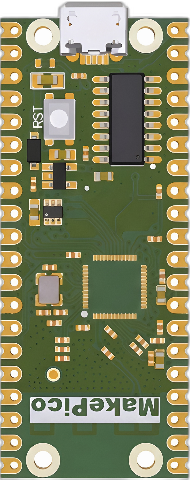
The ESP32 MakerPico is a compact and versatile development board built around the ESP32 microcontroller. It features integrated Wi-Fi and Bluetooth capabilities, making it an excellent choice for IoT (Internet of Things) applications. The board is designed for rapid prototyping and supports a wide range of sensors, modules, and peripherals. Its small form factor and robust feature set make it ideal for projects requiring wireless communication, data processing, and control.
Explore Projects Built with ESP32 MakerPico


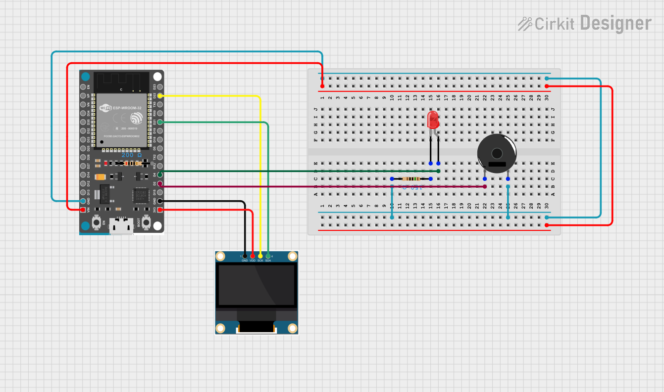
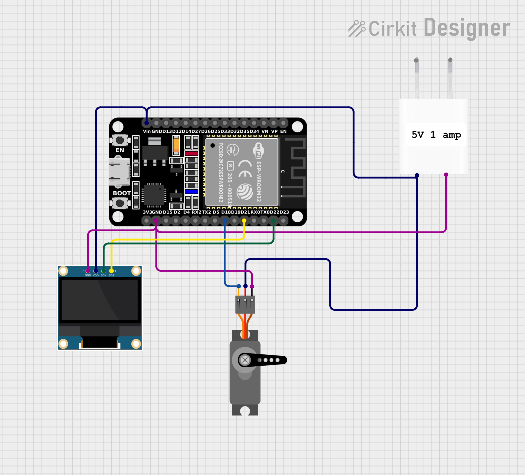
Explore Projects Built with ESP32 MakerPico
Common Applications and Use Cases
- IoT devices and smart home automation
- Wireless sensor networks
- Remote monitoring and control systems
- Wearable devices
- Robotics and automation
- Educational projects and prototyping
Technical Specifications
Key Technical Details
- Microcontroller: ESP32 dual-core processor
- Clock Speed: Up to 240 MHz
- Flash Memory: 4 MB
- SRAM: 520 KB
- Connectivity: Wi-Fi (802.11 b/g/n), Bluetooth 4.2 (Classic and BLE)
- Operating Voltage: 3.3V
- Input Voltage Range: 5V (via USB-C)
- GPIO Pins: 20 (configurable as digital I/O, PWM, I2C, SPI, UART, etc.)
- ADC Channels: 12-bit resolution, up to 18 channels
- DAC Channels: 2 (8-bit resolution)
- Interfaces: I2C, SPI, UART, PWM, ADC, DAC
- USB Interface: USB-C for power and programming
- Dimensions: 51mm x 21mm
Pin Configuration and Descriptions
The ESP32 MakerPico features a total of 20 GPIO pins, which are multifunctional and can be configured for various purposes. Below is the pinout description:
| Pin | Name | Function |
|---|---|---|
| 1 | GND | Ground |
| 2 | 3V3 | 3.3V power output |
| 3 | GPIO0 | General-purpose I/O, boot mode selection |
| 4 | GPIO1 (TX) | UART TX (Serial communication) |
| 5 | GPIO3 (RX) | UART RX (Serial communication) |
| 6 | GPIO4 | General-purpose I/O, PWM, ADC |
| 7 | GPIO5 | General-purpose I/O, PWM, ADC |
| 8 | GPIO12 | General-purpose I/O, ADC, touch input |
| 9 | GPIO13 | General-purpose I/O, ADC, touch input |
| 10 | GPIO14 | General-purpose I/O, ADC, touch input |
| 11 | GPIO15 | General-purpose I/O, ADC, touch input |
| 12 | GPIO16 | General-purpose I/O, ADC, touch input |
| 13 | GPIO17 | General-purpose I/O, ADC, touch input |
| 14 | GPIO18 (SCK) | SPI Clock |
| 15 | GPIO19 (MISO) | SPI Master-In-Slave-Out |
| 16 | GPIO21 (MOSI) | SPI Master-Out-Slave-In |
| 17 | GPIO22 (SCL) | I2C Clock |
| 18 | GPIO23 (SDA) | I2C Data |
| 19 | EN | Enable pin (active high, resets the board when pulled low) |
| 20 | VIN | Input voltage (5V via USB-C or external power source) |
Usage Instructions
How to Use the ESP32 MakerPico in a Circuit
Powering the Board:
- Connect the board to a computer or power source using a USB-C cable.
- Alternatively, supply 5V to the VIN pin for external power.
Programming the Board:
- Install the ESP32 board package in the Arduino IDE or use the ESP-IDF framework.
- Select "ESP32 Dev Module" as the board in the Arduino IDE.
- Connect the board to your computer and upload your code.
Connecting Peripherals:
- Use the GPIO pins to connect sensors, actuators, or other modules.
- Ensure that the voltage levels of connected devices are compatible with the 3.3V logic of the ESP32.
Wireless Communication:
- Use the built-in Wi-Fi and Bluetooth capabilities for wireless data transmission.
- Configure the network settings in your code to connect to a Wi-Fi network or pair with Bluetooth devices.
Important Considerations and Best Practices
- Avoid supplying more than 3.3V to the GPIO pins to prevent damage to the board.
- Use level shifters when interfacing with 5V devices.
- Ensure proper grounding when connecting external components.
- Use decoupling capacitors for stable power supply to sensitive components.
- When using ADC pins, note that the input voltage range is 0-3.3V.
Example Code for Arduino UNO Integration
Below is an example of using the ESP32 MakerPico to read data from a DHT11 temperature and humidity sensor and send it to a serial monitor:
#include <WiFi.h>
#include <DHT.h>

// Define DHT sensor type and pin
#define DHTPIN 4  // GPIO4 is connected to the DHT sensor
#define DHTTYPE DHT11

DHT dht(DHTPIN, DHTTYPE);

void setup() {
  Serial.begin(115200);  // Initialize serial communication
  dht.begin();           // Initialize the DHT sensor
  Serial.println("DHT11 Sensor Test");
}

void loop() {
  delay(2000);  // Wait 2 seconds between readings

  // Read temperature and humidity values
  float humidity = dht.readHumidity();
  float temperature = dht.readTemperature();

  // Check if readings are valid
  if (isnan(humidity) || isnan(temperature)) {
    Serial.println("Failed to read from DHT sensor!");
    return;
  }

  // Print the readings to the serial monitor
  Serial.print("Humidity: ");
  Serial.print(humidity);
  Serial.print("%  Temperature: ");
  Serial.print(temperature);
  Serial.println("°C");
}
Troubleshooting and FAQs
Common Issues and Solutions
Board Not Detected by Computer:
- Ensure the USB-C cable is a data cable, not just a charging cable.
- Check if the correct COM port is selected in the Arduino IDE.
Code Upload Fails:
- Verify that the correct board and port are selected in the IDE.
- Press and hold the "BOOT" button on the board while uploading the code.
Wi-Fi Connection Issues:
- Double-check the SSID and password in your code.
- Ensure the Wi-Fi network is within range and operational.
GPIO Pin Malfunction:
- Confirm that the pin is not being used for another function (e.g., boot mode).
- Check for short circuits or incorrect wiring.
FAQs
Can I power the ESP32 MakerPico with a battery?
Yes, you can use a 3.7V LiPo battery with a suitable voltage regulator or connect a 5V source to the VIN pin.What is the maximum current output of the 3.3V pin?
The 3.3V pin can supply up to 500mA, depending on the input power source.Does the board support OTA (Over-The-Air) updates?
Yes, the ESP32 MakerPico supports OTA updates for wireless firmware uploads.Can I use the board with MicroPython?
Yes, the ESP32 MakerPico is compatible with MicroPython. You can flash the MicroPython firmware to the board and use it for development.