How to Use Converter 24V to 6V 40A: Examples, Pinouts, and Specs
Introduction
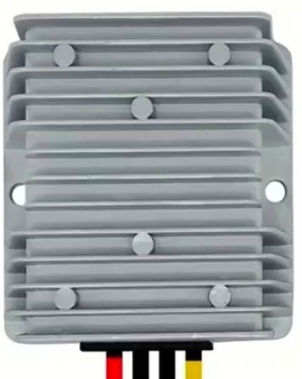
The Converter 24V to 6V 40A is a DC-DC step-down power converter designed to reduce a 24V input voltage to a stable 6V output. With a maximum current capacity of 40 amps, this converter is ideal for powering devices and systems that require a lower voltage supply, such as automotive electronics, industrial equipment, and high-power LED lighting systems. Its robust design ensures reliable performance in demanding applications.
Explore Projects Built with Converter 24V to 6V 40A


Explore Projects Built with Converter 24V to 6V 40A
Common Applications
- Automotive systems (e.g., powering 6V devices from a 24V vehicle battery)
- Industrial control systems
- High-power LED lighting
- Robotics and motor controllers
- Battery charging for 6V systems
Technical Specifications
Key Specifications
| Parameter | Value |
|---|---|
| Input Voltage Range | 20V to 30V |
| Output Voltage | 6V (fixed) |
| Maximum Output Current | 40A |
| Efficiency | Up to 95% |
| Operating Temperature | -40°C to +85°C |
| Protection Features | Overcurrent, Overvoltage, |
| Overtemperature, Short Circuit |
Pin Configuration and Descriptions
| Pin Name | Description |
|---|---|
| VIN+ | Positive input terminal (connect to 24V) |
| VIN- | Negative input terminal (connect to ground) |
| VOUT+ | Positive output terminal (provides 6V) |
| VOUT- | Negative output terminal (connect to ground) |
Usage Instructions
How to Use the Converter in a Circuit
- Input Connection: Connect the VIN+ and VIN- terminals to a 24V DC power source. Ensure the input voltage is within the specified range (20V to 30V).
- Output Connection: Connect the VOUT+ and VOUT- terminals to the load requiring 6V. Verify that the load does not exceed the maximum current rating of 40A.
- Wiring: Use appropriately rated wires to handle the high current (40A). Thicker wires reduce voltage drop and heat generation.
- Mounting: Secure the converter to a heat-dissipating surface or use additional cooling if operating near the maximum current limit.
- Testing: Before connecting the load, measure the output voltage with a multimeter to ensure it is stable at 6V.
Important Considerations
- Heat Management: At high currents, the converter may generate significant heat. Use proper ventilation or a heatsink to maintain safe operating temperatures.
- Input Voltage: Ensure the input voltage remains within the specified range to avoid damage to the converter.
- Polarity: Double-check the polarity of all connections to prevent short circuits or damage.
- Fuse Protection: Consider adding a fuse on the input side to protect the converter and connected devices from overcurrent conditions.
Example: Using the Converter with an Arduino UNO
If you are powering an Arduino UNO and other 6V peripherals from a 24V source, you can use this converter to step down the voltage. Below is an example of how to connect the converter:
- Connect the VIN+ and VIN- terminals to the 24V power source.
- Connect the VOUT+ terminal to the Arduino's VIN pin (which accepts 6V to 12V).
- Connect the VOUT- terminal to the Arduino's GND pin.
Here is a simple Arduino code snippet to blink an LED while powered by the converter:
// This code blinks an LED connected to pin 13 of the Arduino UNO.
// Ensure the Arduino is powered via the 6V output of the converter.

void setup() {
  pinMode(13, OUTPUT); // Set pin 13 as an output
}

void loop() {
  digitalWrite(13, HIGH); // Turn the LED on
  delay(1000);            // Wait for 1 second
  digitalWrite(13, LOW);  // Turn the LED off
  delay(1000);            // Wait for 1 second
}
Troubleshooting and FAQs
Common Issues and Solutions
| Issue | Possible Cause | Solution |
|---|---|---|
| No output voltage | Incorrect wiring or loose connections | Verify all connections and polarity. |
| Output voltage fluctuates | Input voltage is unstable | Use a regulated 24V power source. |
| Converter overheats | Excessive load or poor ventilation | Reduce load or improve cooling. |
| Load not functioning properly | Load exceeds current rating | Ensure load is within 40A limit. |
FAQs
Q: Can I use this converter with a 12V input?
A: No, the input voltage must be within the range of 20V to 30V for proper operation.
Q: Is the output voltage adjustable?
A: No, the output voltage is fixed at 6V.
Q: What type of fuse should I use for protection?
A: Use a fuse rated slightly above the maximum input current, considering the input voltage and load requirements.
Q: Can I connect multiple converters in parallel for higher current?
A: It is not recommended to connect converters in parallel unless specifically designed for such operation, as it may cause instability or damage.
By following this documentation, you can safely and effectively use the Converter 24V to 6V 40A in your projects.