How to Use flame sensor: Examples, Pinouts, and Specs
Introduction
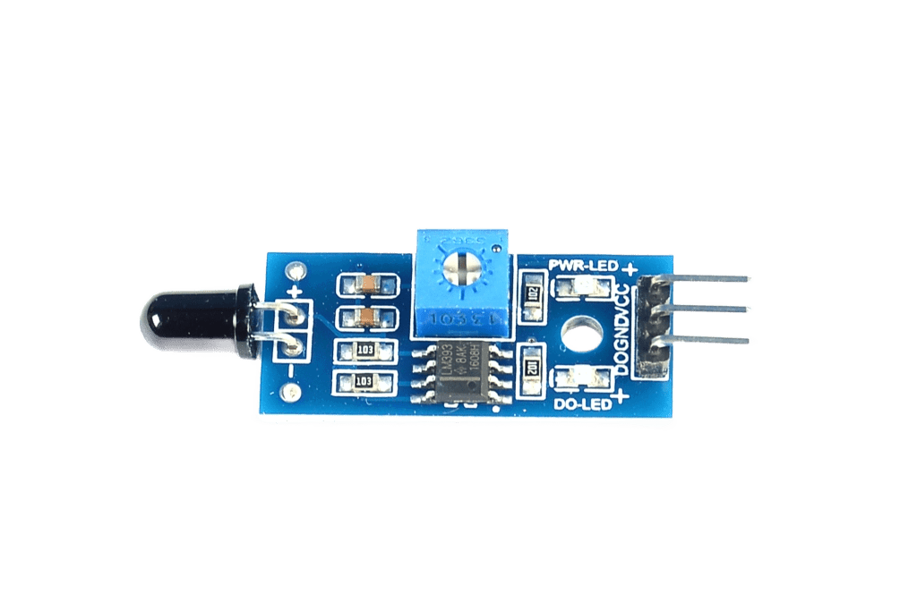
A flame sensor is a device designed to detect the presence of a flame or fire by sensing the infrared (IR) radiation emitted by the flame. It is a critical component in fire detection and safety systems, where it can trigger alarms, activate fire suppression systems, or shut down equipment to prevent damage or hazards. Flame sensors are widely used in industrial safety systems, gas-powered appliances, and robotics projects.
Explore Projects Built with flame sensor
Explore Projects Built with flame sensor
Common Applications and Use Cases
- Fire detection and alarm systems
- Industrial safety systems for gas burners and boilers
- Robotics projects for flame tracking
- Gas-powered appliances (e.g., stoves, heaters)
- Fire suppression systems
Technical Specifications
Below are the key technical details of a typical flame sensor module:
| Parameter | Value |
|---|---|
| Operating Voltage | 3.3V to 5V |
| Detection Range | 760 nm to 1100 nm (IR wavelength) |
| Detection Angle | 60° |
| Digital Output Voltage | 0V (no flame), 5V (flame detected) |
| Analog Output Voltage | Proportional to flame intensity |
| Response Time | ≤ 15 ms |
| Operating Temperature | -25°C to 85°C |
Pin Configuration and Descriptions
The flame sensor module typically has three or four pins. Below is the pinout description:
| Pin | Name | Description |
|---|---|---|
| 1 | VCC | Power supply pin (3.3V to 5V). Connect to the positive terminal of the power source. |
| 2 | GND | Ground pin. Connect to the ground terminal of the power source. |
| 3 | DOUT | Digital output pin. Outputs HIGH (5V) when a flame is detected, LOW (0V) otherwise. |
| 4 | AOUT | Analog output pin. Outputs a voltage proportional to the intensity of the flame. |
Usage Instructions
How to Use the Flame Sensor in a Circuit
- Connect the Power Supply:
- Connect the VCC pin to a 3.3V or 5V power source.
- Connect the GND pin to the ground of the power source.
- Connect the Output Pins:
- For digital output, connect the DOUT pin to a digital input pin on your microcontroller or logic circuit.
- For analog output, connect the AOUT pin to an analog input pin on your microcontroller.
- Adjust the Sensitivity:
- Use the onboard potentiometer to adjust the sensitivity of the flame sensor. Turn it clockwise to increase sensitivity and counterclockwise to decrease it.
- Position the Sensor:
- Place the sensor in a location where it has a clear line of sight to the flame. Ensure the detection angle (60°) covers the target area.
Important Considerations and Best Practices
- Avoid exposing the sensor to direct sunlight or other strong IR sources, as this may cause false detections.
- Ensure the sensor is not obstructed by objects that block IR radiation.
- Use proper shielding or enclosures to protect the sensor from environmental factors like dust or moisture.
- When using the analog output, calibrate the sensor to account for ambient IR levels.
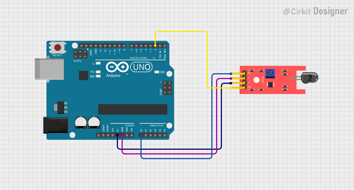
Example: Connecting to an Arduino UNO
Below is an example of how to connect and use the flame sensor with an Arduino UNO:
Circuit Connections
- Connect the VCC pin of the flame sensor to the 5V pin on the Arduino.
- Connect the GND pin of the flame sensor to the GND pin on the Arduino.
- Connect the DOUT pin of the flame sensor to digital pin 2 on the Arduino.
Arduino Code
// Flame Sensor Example with Arduino UNO
// This code reads the digital output of the flame sensor and turns on an LED
// if a flame is detected.

const int flameSensorPin = 2; // Digital pin connected to DOUT of the flame sensor
const int ledPin = 13;        // Built-in LED pin on Arduino

void setup() {
  pinMode(flameSensorPin, INPUT); // Set flame sensor pin as input
  pinMode(ledPin, OUTPUT);        // Set LED pin as output
  Serial.begin(9600);             // Initialize serial communication
}

void loop() {
  int flameDetected = digitalRead(flameSensorPin); // Read the flame sensor output

  if (flameDetected == HIGH) {
    // Flame detected
    digitalWrite(ledPin, HIGH); // Turn on the LED
    Serial.println("Flame detected!");
  } else {
    // No flame detected
    digitalWrite(ledPin, LOW);  // Turn off the LED
    Serial.println("No flame detected.");
  }

  delay(500); // Wait for 500ms before the next reading
}
Troubleshooting and FAQs
Common Issues and Solutions
False Detections in Bright Environments:
- Cause: Strong ambient light or IR sources (e.g., sunlight, incandescent bulbs).
- Solution: Shield the sensor from direct light or use it in controlled environments.
No Detection of Flame:
- Cause: Incorrect positioning or low sensitivity.
- Solution: Adjust the potentiometer to increase sensitivity and ensure the sensor has a clear line of sight to the flame.
Unstable Output:
- Cause: Electrical noise or unstable power supply.
- Solution: Use decoupling capacitors near the sensor's power pins and ensure a stable power source.
Analog Output Not Working:
- Cause: Incorrect connection or damaged sensor.
- Solution: Verify the AOUT pin connection and test the sensor with a multimeter.
FAQs
Q1: Can the flame sensor detect flames through glass?
A1: No, most flame sensors cannot detect flames through glass, as glass blocks a significant portion of IR radiation.
Q2: What is the maximum distance for flame detection?
A2: The detection range depends on the intensity of the flame and the sensor's sensitivity. Typically, it can detect flames up to 1 meter away.
Q3: Can the flame sensor detect other heat sources?
A3: The flame sensor is designed to detect IR radiation from flames. However, it may respond to other strong IR sources, such as incandescent bulbs or sunlight.
Q4: Is the flame sensor waterproof?
A4: No, the flame sensor is not waterproof. Use it in dry environments or protect it with a suitable enclosure.