How to Use LUX DRIVE 500mA F004-D-P-500: Examples, Pinouts, and Specs
Introduction
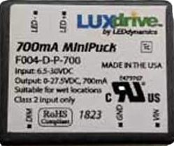
The LUX DRIVE 500mA F004-D-P-500 is a compact and efficient LED driver designed to deliver a constant current of 500mA. This component is ideal for powering LED lighting applications, ensuring consistent brightness and optimal performance. Its robust design and high efficiency make it suitable for a wide range of applications, including residential, commercial, and industrial lighting systems.
Explore Projects Built with LUX DRIVE 500mA F004-D-P-500


Explore Projects Built with LUX DRIVE 500mA F004-D-P-500
Common Applications and Use Cases
- LED strip lighting
- Architectural lighting
- Backlighting for displays
- Automotive LED systems
- General-purpose LED lighting projects
Technical Specifications
The following table outlines the key technical details of the LUX DRIVE 500mA F004-D-P-500:
| Parameter | Value |
|---|---|
| Manufacturer | LUX |
| Part Number | F004-D-P-500 |
| Output Current | 500mA (constant) |
| Input Voltage Range | 6V to 30V DC |
| Output Voltage Range | 2V to 28V DC |
| Efficiency | Up to 95% |
| Dimming Support | PWM and Analog Dimming |
| Operating Temperature | -40°C to +85°C |
| Dimensions | 25mm x 15mm x 10mm |
| Protection Features | Overcurrent, Overvoltage, |
| and Thermal Shutdown |
Pin Configuration and Descriptions
The LUX DRIVE 500mA F004-D-P-500 has a simple pinout for easy integration into circuits. The table below describes each pin:
| Pin Name | Pin Type | Description |
|---|---|---|
| VIN | Power Input | Connect to the positive terminal of the DC power supply. |
| GND | Ground | Connect to the negative terminal of the DC power supply. |
| LED+ | Output Positive | Connect to the positive terminal of the LED load. |
| LED- | Output Negative | Connect to the negative terminal of the LED load. |
| DIM | Control Input | Optional dimming input for PWM or analog control. |
Usage Instructions
How to Use the Component in a Circuit
- Power Supply: Connect a DC power supply (6V to 30V) to the
VINandGNDpins. Ensure the power supply can provide sufficient current for the LED load. - LED Connection: Connect the LED load to the
LED+andLED-pins. Ensure the LED's forward voltage is within the output voltage range (2V to 28V). - Dimming (Optional): If dimming is required, connect a PWM signal (0-100% duty cycle) or an analog voltage (0-2.5V) to the
DIMpin. Leave theDIMpin unconnected for full brightness. - Thermal Management: Ensure adequate ventilation or heatsinking if the driver operates in high-temperature environments or under heavy loads.
Important Considerations and Best Practices
- Input Voltage: Always ensure the input voltage is within the specified range (6V to 30V). Exceeding this range may damage the driver.
- LED Compatibility: Verify that the LED load's forward voltage and current requirements match the driver's specifications.
- Dimming: Use a clean PWM signal or stable analog voltage for dimming to avoid flickering.
- Protection Features: The driver includes overcurrent, overvoltage, and thermal shutdown protection. However, avoid operating the driver near its maximum limits for prolonged periods.
Example: Connecting to an Arduino UNO
The LUX DRIVE 500mA F004-D-P-500 can be controlled using an Arduino UNO for dimming purposes. Below is an example code snippet to control the brightness of an LED using PWM:
// Define the PWM pin connected to the DIM pin of the LUX DRIVE
const int dimPin = 9; // Use pin 9 for PWM output

void setup() {
  pinMode(dimPin, OUTPUT); // Set the pin as an output
}

void loop() {
  // Gradually increase brightness
  for (int brightness = 0; brightness <= 255; brightness++) {
    analogWrite(dimPin, brightness); // Write PWM signal to DIM pin
    delay(10); // Small delay for smooth transition
  }

  // Gradually decrease brightness
  for (int brightness = 255; brightness >= 0; brightness--) {
    analogWrite(dimPin, brightness); // Write PWM signal to DIM pin
    delay(10); // Small delay for smooth transition
  }
}
Note: Ensure the Arduino's ground (
GND) is connected to theGNDpin of the LUX DRIVE for proper operation.
Troubleshooting and FAQs
Common Issues and Solutions
LED Does Not Light Up:
- Cause: Incorrect wiring or insufficient input voltage.
- Solution: Double-check all connections and ensure the input voltage is within the specified range.
Flickering LED:
- Cause: Unstable PWM signal or noisy power supply.
- Solution: Use a clean PWM signal for dimming and ensure the power supply is stable.
Driver Overheating:
- Cause: Insufficient ventilation or operating near maximum limits.
- Solution: Improve ventilation or add a heatsink to the driver.
Dimming Not Working:
- Cause: Incorrect PWM or analog voltage levels.
- Solution: Verify the PWM duty cycle (0-100%) or analog voltage (0-2.5V) applied to the
DIMpin.
FAQs
Q1: Can I use this driver with multiple LEDs?
A1: Yes, you can connect multiple LEDs in series, provided their combined forward voltage is within the output voltage range (2V to 28V).
Q2: What happens if the input voltage exceeds 30V?
A2: Exceeding the input voltage range may damage the driver. Always use a regulated power supply within the specified range.
Q3: Is the driver waterproof?
A3: No, the LUX DRIVE 500mA F004-D-P-500 is not waterproof. Use appropriate enclosures for outdoor or wet environments.
Q4: Can I use this driver for RGB LEDs?
A4: This driver is designed for single-color LEDs. For RGB LEDs, you will need separate drivers for each color channel.
By following this documentation, users can effectively integrate the LUX DRIVE 500mA F004-D-P-500 into their LED lighting projects, ensuring reliable and efficient operation.