How to Use 20X20X5 24V Blower Fan: Examples, Pinouts, and Specs
Introduction
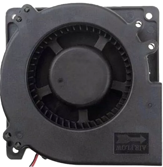
The 20X20X5 24V Blower Fan (Manufacturer: MANTECH, Part ID: BLOWER) is a compact and efficient fan designed to provide targeted airflow in confined spaces. With its 24V operating voltage, this blower fan is ideal for cooling electronic components, dissipating heat in small enclosures, or enhancing ventilation in compact systems. Its small form factor (20mm x 20mm x 5mm) makes it suitable for applications where space is limited.
Explore Projects Built with 20X20X5 24V Blower Fan


Explore Projects Built with 20X20X5 24V Blower Fan
Common Applications
- Cooling microcontrollers, processors, or other heat-sensitive components.
- Ventilation in small electronic enclosures or 3D printer housings.
- Enhancing airflow in robotics or embedded systems.
- Compact cooling solutions for power supplies or LED drivers.
Technical Specifications
Below are the key technical details of the 20X20X5 24V Blower Fan:
| Parameter | Value |
|---|---|
| Manufacturer | MANTECH |
| Part ID | BLOWER |
| Dimensions | 20mm x 20mm x 5mm |
| Operating Voltage | 24V DC |
| Operating Current | 0.08A (typical) |
| Power Consumption | 1.92W |
| Airflow | 2.5 CFM (Cubic Feet per Minute) |
| Noise Level | 25 dBA (typical) |
| Bearing Type | Sleeve Bearing |
| Connector Type | 2-pin JST |
| Weight | 5 grams |
Pin Configuration and Descriptions
The 20X20X5 24V Blower Fan has a simple 2-pin JST connector for power input. The pin configuration is as follows:
| Pin | Wire Color | Description |
|---|---|---|
| 1 | Red | Positive terminal (+24V DC) |
| 2 | Black | Ground (GND) |
Usage Instructions
How to Use the Blower Fan in a Circuit
- Power Supply: Ensure you have a regulated 24V DC power supply capable of providing at least 0.1A of current to power the fan.
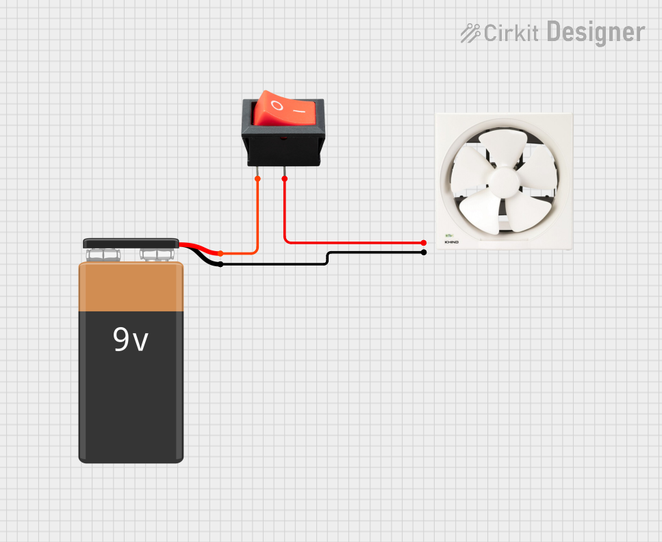
- Connection: Connect the red wire to the positive terminal of the power supply and the black wire to the ground terminal.
- Mounting: Secure the fan in place using screws or adhesive, ensuring that the airflow direction aligns with your cooling or ventilation requirements. The airflow direction is typically indicated by an arrow on the fan housing.
- Operation: Once powered, the fan will begin operating immediately, providing consistent airflow.
Important Considerations and Best Practices
- Voltage Tolerance: Do not exceed the rated 24V DC input, as overvoltage can damage the fan.
- Current Supply: Ensure the power supply can deliver sufficient current (at least 0.1A) to avoid underpowering the fan.
- Orientation: Install the fan in a way that optimizes airflow for your application. Avoid obstructing the intake or exhaust vents.
- Noise Reduction: If noise is a concern, consider using vibration-dampening mounts to minimize operational noise.
- Maintenance: Periodically clean the fan to remove dust or debris that may accumulate and reduce performance.
Example: Connecting to an Arduino UNO
While the fan operates at 24V, you can control it using an Arduino UNO and a transistor or MOSFET as a switch. Below is an example circuit and code to control the fan using a PWM signal:
Circuit Setup
- Connect the fan's red wire to the 24V power supply.
- Connect the fan's black wire to the drain of an N-channel MOSFET (e.g., IRF540N).
- Connect the source of the MOSFET to ground.
- Connect the MOSFET's gate to an Arduino PWM pin (e.g., pin 9) through a 220-ohm resistor.
- Connect the ground of the 24V power supply to the Arduino's ground.
Arduino Code
// Arduino code to control the 20X20X5 24V Blower Fan using PWM
// Ensure the fan is connected via a MOSFET to handle the 24V power.

const int fanPin = 9; // PWM pin connected to the MOSFET gate

void setup() {
  pinMode(fanPin, OUTPUT); // Set the fan control pin as an output
}

void loop() {
  // Example: Gradually increase and decrease fan speed
  for (int speed = 0; speed <= 255; speed++) {
    analogWrite(fanPin, speed); // Set fan speed (0-255)
    delay(10); // Wait 10ms before increasing speed
  }
  for (int speed = 255; speed >= 0; speed--) {
    analogWrite(fanPin, speed); // Decrease fan speed
    delay(10); // Wait 10ms before decreasing speed
  }
}
Note: The Arduino cannot directly power the fan due to its 24V requirement. Always use a MOSFET or transistor to switch the fan on and off.
Troubleshooting and FAQs
Common Issues and Solutions
| Issue | Possible Cause | Solution |
|---|---|---|
| Fan does not spin | No power or incorrect wiring | Verify the power supply and wiring. Ensure the red wire is connected to +24V and the black wire to GND. |
| Fan spins slowly or intermittently | Insufficient current from the power supply | Use a power supply capable of providing at least 0.1A. |
| Excessive noise during operation | Dust buildup or improper mounting | Clean the fan and ensure it is securely mounted. Use vibration-dampening mounts if needed. |
| Fan overheats or stops working | Overvoltage or prolonged operation at high load | Ensure the input voltage does not exceed 24V. Allow the fan to cool if it overheats. |
FAQs
Can I power the fan with a lower voltage?
- The fan may operate at a lower voltage (e.g., 12V), but the airflow will be reduced, and performance may not meet specifications.
Can I control the fan speed?
- Yes, you can control the fan speed using a PWM signal and a MOSFET or transistor. Refer to the example Arduino code above.
Is the fan waterproof?
- No, the fan is not waterproof. Avoid exposing it to moisture or liquids.
What is the expected lifespan of the fan?
- The fan has an estimated lifespan of 30,000 hours under normal operating conditions.
By following this documentation, you can effectively integrate the 20X20X5 24V Blower Fan into your projects for reliable and efficient cooling or ventilation.