How to Use Motor V2: Examples, Pinouts, and Specs
Introduction
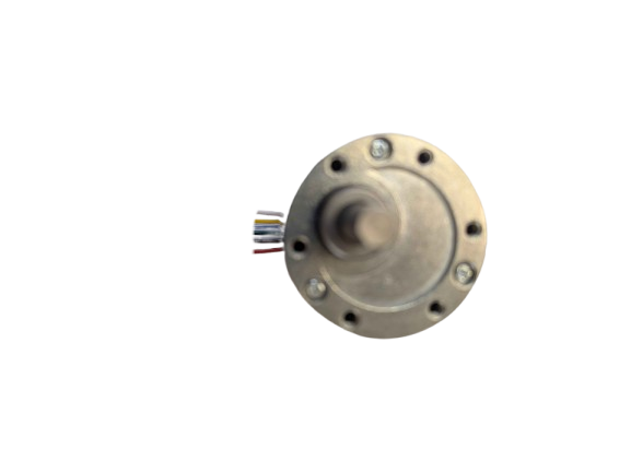
The Motor V2 (Manufacturer Part ID: FIT0186) by DFROBOT is an upgraded version of a standard electric motor, designed to deliver enhanced efficiency and performance. This motor is ideal for applications requiring precise speed control, high torque, and durability, making it a popular choice in robotics, automation, and other electromechanical systems.
Explore Projects Built with Motor V2
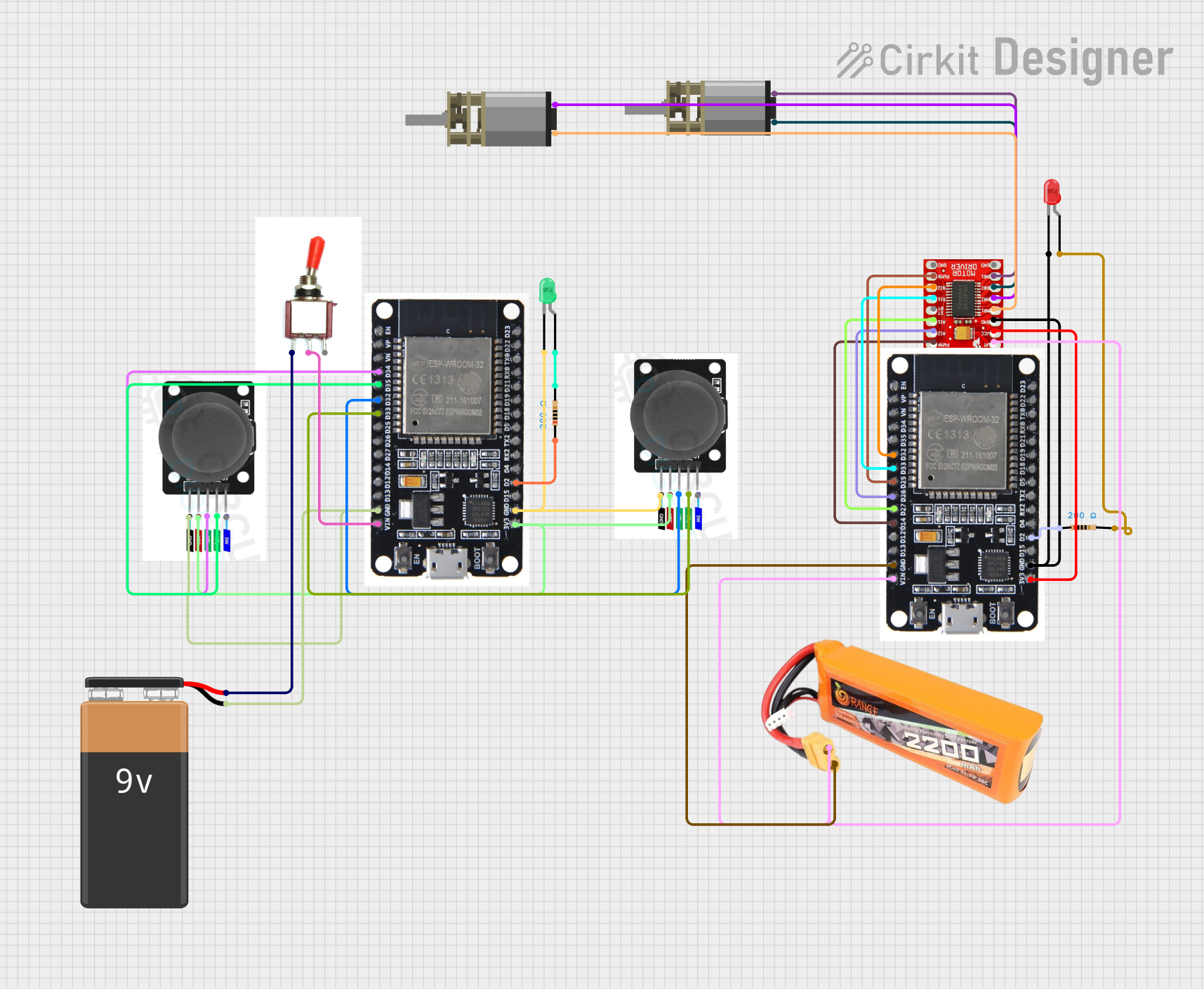
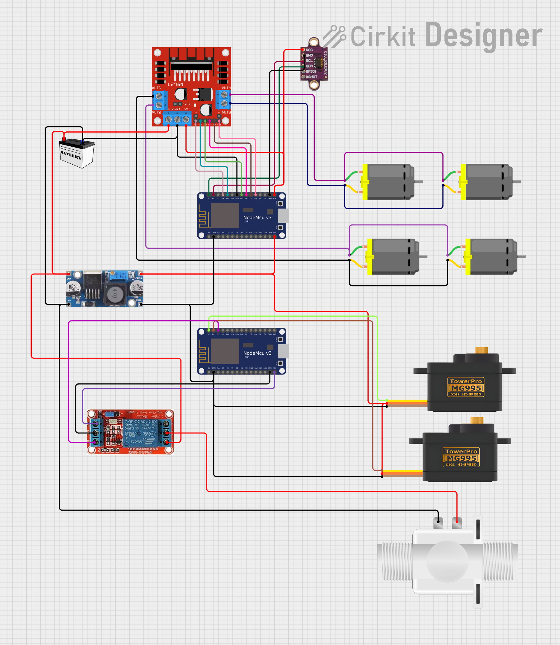
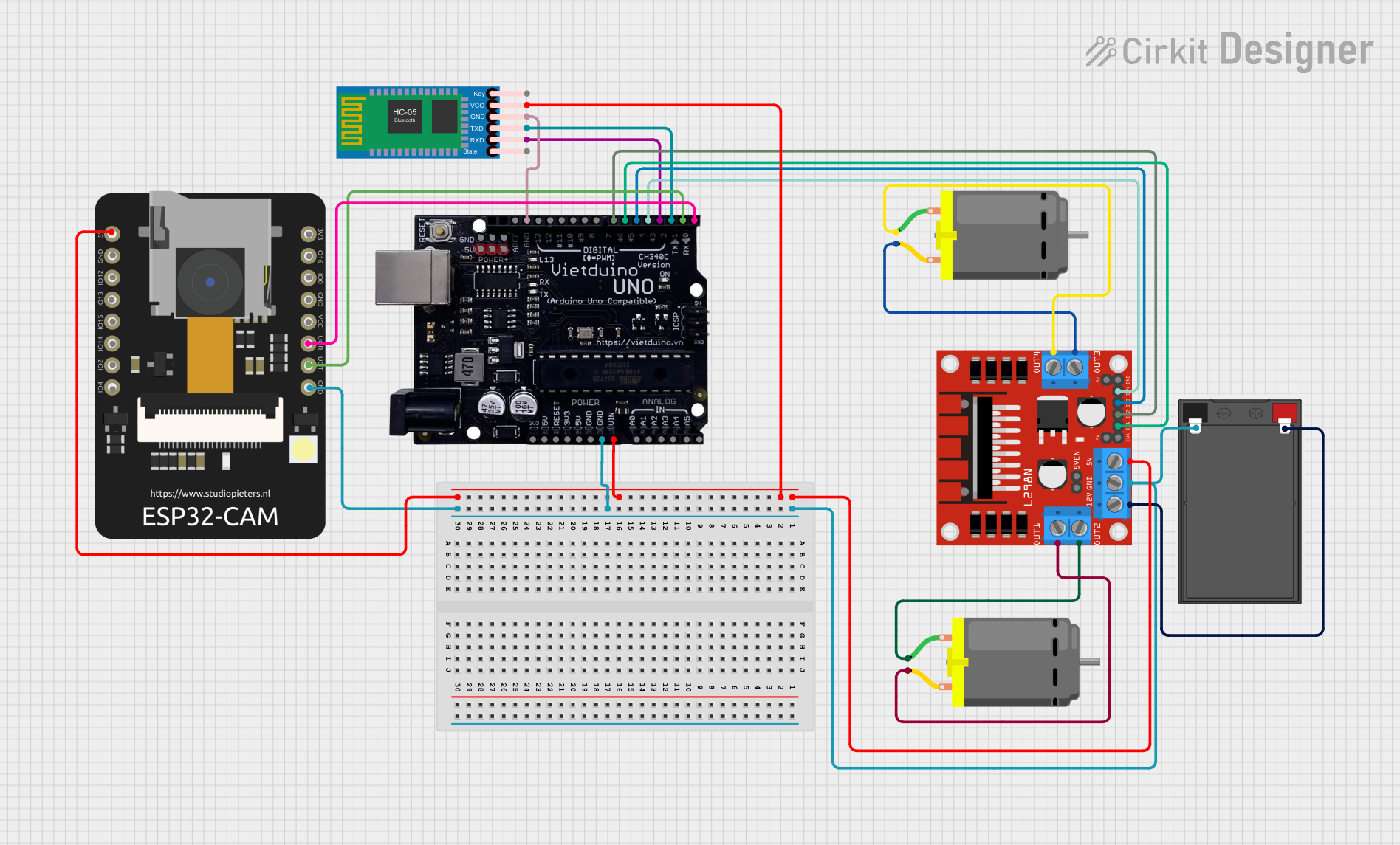

Explore Projects Built with Motor V2
Common Applications
- Robotics: Driving wheels, robotic arms, and actuators.
- Automation: Conveyor belts, automated doors, and industrial machinery.
- DIY Projects: Remote-controlled vehicles, drones, and hobbyist creations.
- Educational Kits: Teaching motor control and electronics concepts.
Technical Specifications
The following table outlines the key technical details of the Motor V2:
| Parameter | Value |
|---|---|
| Operating Voltage | 6V to 12V |
| Rated Current | 1.5A (max) |
| Stall Current | 3.2A |
| Rated Torque | 1.2 kg·cm |
| Stall Torque | 2.5 kg·cm |
| No-Load Speed | 200 RPM (at 12V) |
| Motor Type | Brushed DC Motor |
| Shaft Diameter | 6 mm |
| Dimensions | 50 mm x 30 mm x 20 mm |
| Weight | 120 g |
Pin Configuration and Descriptions
The Motor V2 has two terminals for electrical connections. The table below describes the pin configuration:
| Pin | Description |
|---|---|
| + | Positive terminal for power input (6V-12V). |
| - | Negative terminal for power input (GND). |
Usage Instructions
How to Use the Motor V2 in a Circuit
- Power Supply: Connect the motor to a DC power source within the operating voltage range (6V-12V). Ensure the power supply can handle the motor's current requirements.
- Motor Driver: Use a motor driver (e.g., L298N or TB6612FNG) to control the motor. Directly connecting the motor to a microcontroller is not recommended due to high current draw.
- Polarity: Reversing the polarity of the power supply will reverse the motor's rotation direction.
- PWM Control: Use Pulse Width Modulation (PWM) to control the motor's speed. This can be achieved using a microcontroller like an Arduino.
Important Considerations
- Heat Dissipation: Prolonged operation at high current may cause the motor to heat up. Ensure proper ventilation or heat dissipation mechanisms.
- Current Limiting: Use a motor driver with current limiting features to protect the motor and power supply.
- Load Conditions: Avoid stalling the motor for extended periods, as this can lead to overheating and damage.
Example: Connecting Motor V2 to an Arduino UNO
Below is an example of controlling the Motor V2 using an Arduino UNO and an L298N motor driver:
// Motor V2 Control with Arduino UNO and L298N Motor Driver
// Connect the motor to the L298N motor driver outputs (OUT1 and OUT2).
// Connect the L298N inputs (IN1 and IN2) to Arduino pins 9 and 10.

#define IN1 9  // L298N IN1 connected to Arduino pin 9
#define IN2 10 // L298N IN2 connected to Arduino pin 10
#define ENA 5  // L298N ENA (PWM pin) connected to Arduino pin 5

void setup() {
  pinMode(IN1, OUTPUT); // Set IN1 as output
  pinMode(IN2, OUTPUT); // Set IN2 as output
  pinMode(ENA, OUTPUT); // Set ENA as output
}

void loop() {
  // Rotate motor forward
  digitalWrite(IN1, HIGH); // Set IN1 HIGH
  digitalWrite(IN2, LOW);  // Set IN2 LOW
  analogWrite(ENA, 128);   // Set speed to 50% (PWM value: 128)

  delay(2000); // Run motor for 2 seconds

  // Rotate motor backward
  digitalWrite(IN1, LOW);  // Set IN1 LOW
  digitalWrite(IN2, HIGH); // Set IN2 HIGH
  analogWrite(ENA, 128);   // Set speed to 50% (PWM value: 128)

  delay(2000); // Run motor for 2 seconds

  // Stop motor
  digitalWrite(IN1, LOW);  // Set IN1 LOW
  digitalWrite(IN2, LOW);  // Set IN2 LOW
  analogWrite(ENA, 0);     // Set speed to 0 (motor off)

  delay(2000); // Wait for 2 seconds before repeating
}
Notes:
- Adjust the
analogWritevalue (0-255) to control the motor speed. - Ensure the motor driver is powered with a suitable voltage and current source.
Troubleshooting and FAQs
Common Issues and Solutions
Motor Does Not Spin
- Cause: Insufficient power supply or incorrect wiring.
- Solution: Verify the power supply voltage and current. Check all connections.
Motor Spins in the Wrong Direction
- Cause: Reversed polarity of the motor terminals.
- Solution: Swap the connections to the motor terminals.
Motor Overheats
- Cause: Prolonged operation at high current or stalled motor.
- Solution: Reduce the load on the motor or use a current-limiting driver.
No Speed Control
- Cause: PWM signal not properly configured.
- Solution: Verify the PWM pin and signal from the microcontroller.
FAQs
Can I connect the Motor V2 directly to an Arduino? No, the Motor V2 requires more current than an Arduino can supply. Use a motor driver.
What happens if I exceed the rated voltage? Exceeding the rated voltage can damage the motor and reduce its lifespan.
Can I use the Motor V2 with a battery? Yes, ensure the battery voltage is within the operating range (6V-12V) and can supply sufficient current.
How do I reverse the motor's direction? Swap the polarity of the motor terminals or adjust the motor driver's control signals.
This documentation provides all the necessary details to effectively use the Motor V2 in your projects. For further assistance, refer to the manufacturer's datasheet or support resources.