How to Use sim800l: Examples, Pinouts, and Specs
Introduction
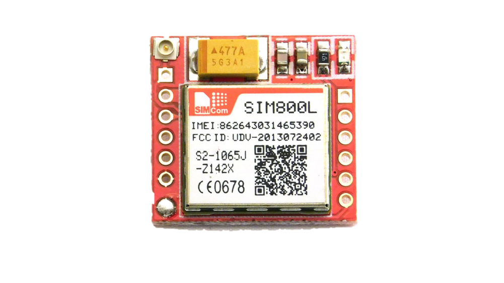
The SIM800L is a compact GSM/GPRS module designed for communication over cellular networks. It supports a wide range of functionalities, including SMS, voice calls, and data transmission via GPRS. With its small size and low power consumption, the SIM800L is an excellent choice for IoT applications, remote monitoring, and embedded systems requiring cellular connectivity.
Explore Projects Built with sim800l


Explore Projects Built with sim800l
Common Applications and Use Cases
- Internet of Things (IoT) devices
- Remote monitoring and control systems
- GPS tracking and fleet management
- Home automation
- SMS-based alert systems
- Voice call-enabled embedded projects
Technical Specifications
Key Technical Details
- Operating Voltage: 3.4V to 4.4V (recommended: 4.0V)
- Power Consumption:
- Idle: ~1mA
- Active (GPRS): ~100mA to 250mA
- Peak (transmission): ~2A
- Frequency Bands: Quad-band 850/900/1800/1900 MHz
- Communication Protocols: AT commands (3GPP TS 27.007, 27.005)
- Data Transmission: GPRS Class 12, up to 85.6 kbps
- SIM Card Support: Micro SIM
- Operating Temperature: -40°C to +85°C
- Dimensions: 25mm x 23mm x 3mm
Pin Configuration and Descriptions
The SIM800L module typically has 12 pins. Below is the pinout and description:
| Pin | Name | Description |
|---|---|---|
| 1 | NET | Network status LED (blinks to indicate GSM status) |
| 2 | VCC | Power supply input (3.4V to 4.4V, recommended 4.0V) |
| 3 | GND | Ground connection |
| 4 | RXD | UART Receive pin (connect to TX of microcontroller) |
| 5 | TXD | UART Transmit pin (connect to RX of microcontroller) |
| 6 | RST | Reset pin (active low, pull low for 100ms to reset the module) |
| 7 | VDD_EXT | External voltage output (not commonly used) |
| 8 | SIM_TXD | SIM card UART transmit (used internally, not typically connected externally) |
| 9 | SIM_RXD | SIM card UART receive (used internally, not typically connected externally) |
| 10 | SIM_RST | SIM card reset (used internally) |
| 11 | SIM_CLK | SIM card clock (used internally) |
| 12 | SIM_DATA | SIM card data (used internally) |
Usage Instructions
How to Use the SIM800L in a Circuit
Power Supply:
- The SIM800L requires a stable power supply of 4.0V. Use a step-down regulator (e.g., LM2596) or a LiPo battery to provide the required voltage.
- Ensure the power supply can handle peak currents of up to 2A during transmission.
Connections:
- Connect the
VCCpin to the 4.0V power supply andGNDto ground. - Connect the
TXDpin of the SIM800L to the RX pin of your microcontroller. - Connect the
RXDpin of the SIM800L to the TX pin of your microcontroller. - Optionally, connect the
RSTpin to a GPIO pin of your microcontroller for resetting the module.
- Connect the
Antenna:
- Attach an external antenna to the SIM800L's antenna connector for better signal reception.
SIM Card:
- Insert a micro SIM card into the SIM card slot. Ensure the SIM card is activated and has sufficient balance for SMS, calls, or data usage.
Communication:
- Use AT commands to communicate with the SIM800L. These commands can be sent via UART from a microcontroller or a USB-to-TTL adapter connected to a PC.
Important Considerations and Best Practices
- Use decoupling capacitors (e.g., 100µF and 10µF) near the power supply pins to stabilize the voltage.
- Avoid using the SIM800L with a 5V logic microcontroller directly. Use a voltage divider or level shifter to convert 5V signals to 3.3V.
- Ensure the antenna is securely connected to avoid poor signal quality.
- Place the module away from high-frequency noise sources to prevent interference.
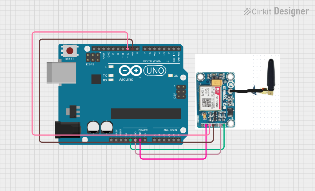
Example: Connecting SIM800L to Arduino UNO
Below is an example of how to send an SMS using the SIM800L and Arduino UNO:
Circuit Connections
- SIM800L
VCCto a 4.0V power supply - SIM800L
GNDto Arduino GND - SIM800L
TXDto Arduino pin 10 (RX) - SIM800L
RXDto Arduino pin 11 (TX) - SIM800L
RSTto Arduino pin 9 (optional)
Arduino Code
#include <SoftwareSerial.h>

// Define RX and TX pins for SoftwareSerial
SoftwareSerial sim800l(10, 11); // RX, TX

void setup() {
  // Initialize serial communication
  Serial.begin(9600); // For debugging
  sim800l.begin(9600); // For SIM800L communication

  // Wait for the module to initialize
  delay(1000);
  Serial.println("Initializing SIM800L...");

  // Send AT command to check communication
  sim800l.println("AT");
  delay(1000);
  while (sim800l.available()) {
    Serial.write(sim800l.read());
  }

  // Send SMS
  sendSMS("+1234567890", "Hello from SIM800L!");
}

void loop() {
  // Nothing to do here
}

void sendSMS(String phoneNumber, String message) {
  sim800l.println("AT+CMGF=1"); // Set SMS mode to text
  delay(1000);

  sim800l.print("AT+CMGS=\"");
  sim800l.print(phoneNumber);
  sim800l.println("\"");
  delay(1000);

  sim800l.print(message); // Message content
  delay(1000);

  sim800l.write(26); // Send Ctrl+Z to send the SMS
  delay(5000);

  Serial.println("SMS sent!");
}
Troubleshooting and FAQs
Common Issues and Solutions
Module Not Responding to AT Commands:
- Ensure the power supply is stable and provides sufficient current (up to 2A).
- Check the RX and TX connections between the SIM800L and the microcontroller.
- Verify the baud rate (default is 9600).
Poor Signal Quality:
- Ensure the antenna is properly connected and positioned in an open area.
- Check the SIM card for proper activation and network coverage.
Module Keeps Restarting:
- This is often caused by an insufficient power supply. Use a power source capable of handling peak currents.
SMS Not Sending:
- Ensure the SIM card has sufficient balance or an active SMS plan.
- Verify the phone number format (e.g., include the country code).
FAQs
Can I use a 5V power supply for the SIM800L? No, the SIM800L requires a voltage between 3.4V and 4.4V. Using 5V can damage the module.
What is the default baud rate of the SIM800L? The default baud rate is 9600, but it can be changed using AT commands.
Can the SIM800L be used for internet access? Yes, the SIM800L supports GPRS for data transmission. You can use AT commands to configure and establish a GPRS connection.
How do I reset the SIM800L? Pull the
RSTpin low for at least 100ms and then release it to reset the module.