Cirkit Designer
Your all-in-one circuit design IDE
Home /
Component Documentation
How to Use ESP32-WROOM: Examples, Pinouts, and Specs
Introduction
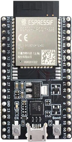
The ESP32-WROOM, manufactured by AZ-Delivery, is a powerful and versatile Wi-Fi and Bluetooth module based on the ESP32 microcontroller. It is designed for a wide range of applications, including Internet of Things (IoT) devices, embedded systems, and smart home automation. The ESP32-WROOM offers robust performance, low power consumption, and a rich set of features, making it an ideal choice for both hobbyists and professionals.
Explore Projects Built with ESP32-WROOM
ESP32-Based GPS Tracker with SD Card Logging and Barometric Sensor

This circuit features an ESP32 Wroom Dev Kit as the main microcontroller, interfaced with an MPL3115A2 sensor for pressure and temperature readings, and a Neo 6M GPS module for location tracking. The ESP32 is also connected to an SD card reader for data logging purposes. A voltage regulator is used to step down the USB power supply to 3.3V, which powers the ESP32, the sensor, and the SD card reader.
ESP32-Based Multi-Sensor Health Monitoring System with Bluetooth Connectivity

This circuit features an ESP32-WROOM-32UE microcontroller as the central processing unit, interfacing with a variety of sensors and modules. It includes a MAX30100 pulse oximeter and heart-rate sensor, an MLX90614 infrared thermometer, an HC-05 Bluetooth module for wireless communication, and a Neo 6M GPS module for location tracking. All components are powered by a common voltage supply and are connected to specific GPIO pins on the ESP32 for data exchange, with the sensors using I2C communication and the modules using UART.
ESP32-Controlled WS2812 RGB LED Strip
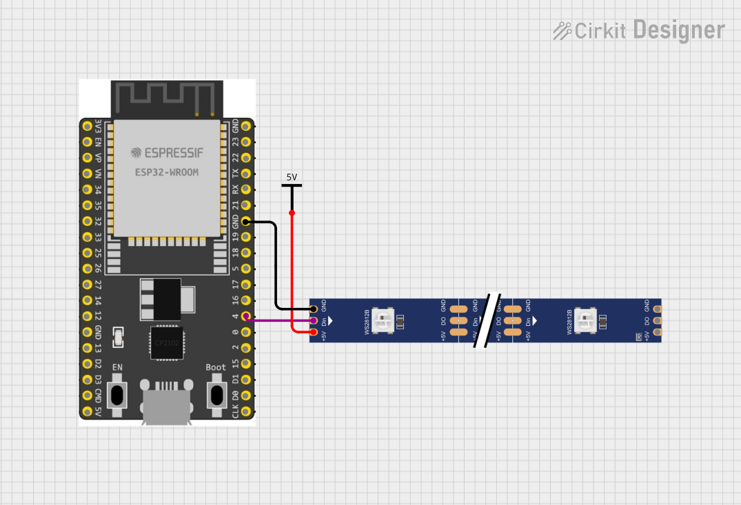
This circuit features an ESP32 Wroom Dev Kit microcontroller connected to a WS2812 RGB LED strip. The ESP32's GPIO 4 is used to send data to the LED strip's data input (DIN), while both the ESP32 and the LED strip share a common ground. A separate Vcc power source is connected to the 5V pin of the LED strip to provide power.
ESP32-Controlled WS2812 RGB LED Strip Lighting System
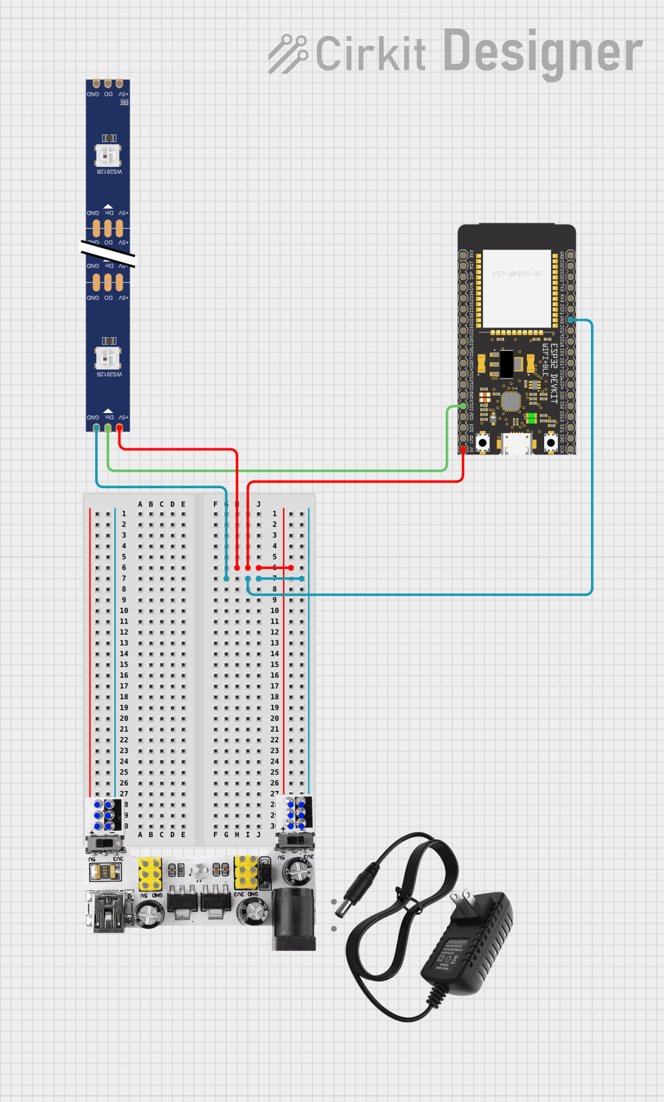
This circuit features an ESP32 Wroom microcontroller connected to a WS2812 RGB LED strip for controlling the LED lighting. The ESP32 is powered by a 5V supply from a breadboard power module, which also provides the 5V needed by the LED strip. The ground connections are shared among all components to complete the circuit, and the ESP32's GPIO13 is used to send data to the LED strip's data input (DIN).
Explore Projects Built with ESP32-WROOM
ESP32-Based GPS Tracker with SD Card Logging and Barometric Sensor
This circuit features an ESP32 Wroom Dev Kit as the main microcontroller, interfaced with an MPL3115A2 sensor for pressure and temperature readings, and a Neo 6M GPS module for location tracking. The ESP32 is also connected to an SD card reader for data logging purposes. A voltage regulator is used to step down the USB power supply to 3.3V, which powers the ESP32, the sensor, and the SD card reader.
ESP32-Based Multi-Sensor Health Monitoring System with Bluetooth Connectivity
This circuit features an ESP32-WROOM-32UE microcontroller as the central processing unit, interfacing with a variety of sensors and modules. It includes a MAX30100 pulse oximeter and heart-rate sensor, an MLX90614 infrared thermometer, an HC-05 Bluetooth module for wireless communication, and a Neo 6M GPS module for location tracking. All components are powered by a common voltage supply and are connected to specific GPIO pins on the ESP32 for data exchange, with the sensors using I2C communication and the modules using UART.
ESP32-Controlled WS2812 RGB LED Strip
This circuit features an ESP32 Wroom Dev Kit microcontroller connected to a WS2812 RGB LED strip. The ESP32's GPIO 4 is used to send data to the LED strip's data input (DIN), while both the ESP32 and the LED strip share a common ground. A separate Vcc power source is connected to the 5V pin of the LED strip to provide power.
ESP32-Controlled WS2812 RGB LED Strip Lighting System
This circuit features an ESP32 Wroom microcontroller connected to a WS2812 RGB LED strip for controlling the LED lighting. The ESP32 is powered by a 5V supply from a breadboard power module, which also provides the 5V needed by the LED strip. The ground connections are shared among all components to complete the circuit, and the ESP32's GPIO13 is used to send data to the LED strip's data input (DIN).
Technical Specifications
Key Technical Details
| Parameter | Value |
|---|---|
| Microcontroller | ESP32 |
| Operating Voltage | 3.0V - 3.6V |
| Flash Memory | 4MB |
| SRAM | 520KB |
| Wi-Fi Standards | 802.11 b/g/n |
| Bluetooth | v4.2 BR/EDR and BLE |
| GPIO Pins | 34 |
| ADC Channels | 18 (12-bit) |
| DAC Channels | 2 (8-bit) |
| UART | 3 |
| SPI | 4 |
| I2C | 2 |
| PWM Channels | 16 |
| Operating Temperature | -40°C to +85°C |
Pin Configuration and Descriptions
| Pin Number | Pin Name | Description |
|---|---|---|
| 1 | EN | Enable (Active High) |
| 2 | IO0 | GPIO0, Boot Mode Select |
| 3 | IO1 | GPIO1, UART0 TXD |
| 4 | IO2 | GPIO2 |
| 5 | IO3 | GPIO3, UART0 RXD |
| 6 | IO4 | GPIO4 |
| 7 | IO5 | GPIO5 |
| 8 | IO6 | GPIO6, Flash SCK |
| 9 | IO7 | GPIO7, Flash SD0 |
| 10 | IO8 | GPIO8, Flash SD1 |
| 11 | IO9 | GPIO9, Flash SD2 |
| 12 | IO10 | GPIO10, Flash SD3 |
| 13 | IO11 | GPIO11, Flash CMD |
| 14 | IO12 | GPIO12, Boot Mode Select |
| 15 | IO13 | GPIO13, HSPI MOSI |
| 16 | IO14 | GPIO14, HSPI CLK |
| 17 | IO15 | GPIO15, HSPI CS0 |
| 18 | IO16 | GPIO16, UART2 RXD |
| 19 | IO17 | GPIO17, UART2 TXD |
| 20 | IO18 | GPIO18, VSPI CLK |
| 21 | IO19 | GPIO19, VSPI MISO |
| 22 | IO21 | GPIO21, I2C SDA |
| 23 | IO22 | GPIO22, I2C SCL |
| 24 | IO23 | GPIO23, VSPI MOSI |
| 25 | IO25 | GPIO25, DAC1 |
| 26 | IO26 | GPIO26, DAC2 |
| 27 | IO27 | GPIO27 |
| 28 | IO32 | GPIO32, ADC1_CH4 |
| 29 | IO33 | GPIO33, ADC1_CH5 |
| 30 | IO34 | GPIO34, ADC1_CH6 |
| 31 | IO35 | GPIO35, ADC1_CH7 |
| 32 | IO36 | GPIO36, ADC1_CH0 |
| 33 | IO39 | GPIO39, ADC1_CH3 |
| 34 | GND | Ground |
| 35 | 3V3 | 3.3V Power Supply |
Usage Instructions
How to Use the ESP32-WROOM in a Circuit
- Power Supply: Connect the 3V3 pin to a 3.3V power supply and the GND pin to ground.
- Boot Mode: To upload code, connect GPIO0 to GND and press the EN button to enter boot mode.
- UART Communication: Use GPIO1 (TXD) and GPIO3 (RXD) for serial communication with a computer or other devices.
- GPIO Usage: Connect sensors, actuators, and other peripherals to the available GPIO pins as needed.
- Wi-Fi and Bluetooth: Use the built-in Wi-Fi and Bluetooth capabilities for wireless communication.
Important Considerations and Best Practices
- Voltage Levels: Ensure that all connected devices operate at 3.3V logic levels to avoid damaging the ESP32-WROOM.
- Power Supply: Use a stable power supply to prevent unexpected resets or malfunctions.
- Heat Dissipation: Provide adequate ventilation or heat sinking if the module operates in high-temperature environments.
- Firmware Updates: Regularly update the firmware to benefit from the latest features and security patches.
Example Code for Arduino UNO
#include <WiFi.h>

// Replace with your network credentials
const char* ssid = "your_SSID";
const char* password = "your_PASSWORD";

void setup() {
  Serial.begin(115200);
  delay(10);

  // Connect to Wi-Fi network
  Serial.println();
  Serial.print("Connecting to ");
  Serial.println(ssid);

  WiFi.begin(ssid, password);

  while (WiFi.status() != WL_CONNECTED) {
    delay(500);
    Serial.print(".");
  }

  Serial.println("");
  Serial.println("WiFi connected.");
  Serial.println("IP address: ");
  Serial.println(WiFi.localIP());
}

void loop() {
  // Add your main code here, to run repeatedly
}
Troubleshooting and FAQs
Common Issues Users Might Face
- Module Not Responding: Ensure that the power supply is stable and all connections are secure.
- Wi-Fi Connection Issues: Verify the SSID and password, and check for interference from other devices.
- Code Upload Failures: Make sure GPIO0 is connected to GND during the upload process and that the correct board and port are selected in the Arduino IDE.
Solutions and Tips for Troubleshooting
- Check Connections: Double-check all wiring and connections to ensure they are correct and secure.
- Use Serial Monitor: Utilize the Serial Monitor in the Arduino IDE to debug and view error messages.
- Update Drivers: Ensure that the USB-to-serial drivers are up to date on your computer.
- Reset Module: If the module becomes unresponsive, press the EN button to reset it.
By following this documentation, users can effectively utilize the ESP32-WROOM module in their projects, leveraging its powerful features for a wide range of applications.