Cirkit Designer Logo
Cirkit Designer
Your all-in-one circuit design IDE
Home / 
Component Documentation

How to Use esp32: Examples, Pinouts, and Specs

Image of esp32
Cirkit Designer LogoDesign with esp32 in Cirkit Designer

Introduction

The ESP32, manufactured by Espressif Systems, is a low-cost, low-power system on a chip (SoC) designed for a wide range of applications. It features integrated Wi-Fi and Bluetooth capabilities, making it an ideal choice for Internet of Things (IoT) projects, smart devices, and embedded systems. The ESP32 is highly versatile, offering dual-core processing, a rich set of peripherals, and support for various communication protocols.

Explore Projects Built with esp32

Use Cirkit Designer to design, explore, and prototype these projects online. Some projects support real-time simulation. Click "Open Project" to start designing instantly!
ESP32-Controlled OLED Display and Servo with DotStar LED Strip and Audio Output
Image of Arena 2: A project utilizing esp32 in a practical application
This circuit features an ESP32 microcontroller driving a variety of components. It controls an OLED display for visual output, a DotStar LED strip for lighting effects, a PAM8403 audio amplifier connected to a speaker for sound output, and a PCA9685 PWM Servo Breakout to manage a servo motor. The ESP32 also interfaces with a piezo speaker for additional sound generation, and the circuit is powered by a 18650 Li-ion battery setup with a TP4056 charging module. The ESP32's embedded code handles the display animation on the OLED.
Cirkit Designer LogoOpen Project in Cirkit Designer
ESP32-Based Sensor Monitoring System with OLED Display and E-Stop
Image of MVP_design: A project utilizing esp32 in a practical application
This circuit features an ESP32 microcontroller that interfaces with a variety of sensors and output devices. It is powered by a Lipo battery through a buck converter, ensuring a stable voltage supply. The ESP32 collects data from a DHT11 temperature and humidity sensor and a vibration sensor, controls a buzzer, and displays information on an OLED screen. An emergency stop (E Stop) is connected for safety purposes, allowing the system to be quickly deactivated.
Cirkit Designer LogoOpen Project in Cirkit Designer
ESP32-Based Environmental Monitoring System with Motion Detection
Image of pro: A project utilizing esp32 in a practical application
This circuit features an ESP32 microcontroller on a baseboard that interfaces with a PIR sensor for motion detection, a DHT22 sensor for measuring temperature and humidity, and a BH1750 sensor for detecting ambient light levels. The ESP32 is configured to communicate with the BH1750 using I2C protocol, with GPIO22 and GPIO21 serving as the SCL and SDA lines, respectively. Power is supplied to the sensors from the ESP32's voltage output pins, and sensor outputs are connected to designated GPIO pins for data acquisition.
Cirkit Designer LogoOpen Project in Cirkit Designer
ESP32-Based Smart Weather Station with Wi-Fi Connectivity
Image of flowchart 3D: A project utilizing esp32 in a practical application
This circuit features an ESP32 microcontroller interfacing with various sensors and modules, including a DHT22 temperature and humidity sensor, an ESP32 CAM for image capture, an I2C LCD screen for display, a load cell with an HX711 interface for weight measurement, and a buzzer for audio alerts. The ESP32 handles data acquisition, processing, and communication with these peripherals to create a multi-functional monitoring and alert system.
Cirkit Designer LogoOpen Project in Cirkit Designer

Explore Projects Built with esp32

Use Cirkit Designer to design, explore, and prototype these projects online. Some projects support real-time simulation. Click "Open Project" to start designing instantly!
Image of Arena 2: A project utilizing esp32 in a practical application
ESP32-Controlled OLED Display and Servo with DotStar LED Strip and Audio Output
This circuit features an ESP32 microcontroller driving a variety of components. It controls an OLED display for visual output, a DotStar LED strip for lighting effects, a PAM8403 audio amplifier connected to a speaker for sound output, and a PCA9685 PWM Servo Breakout to manage a servo motor. The ESP32 also interfaces with a piezo speaker for additional sound generation, and the circuit is powered by a 18650 Li-ion battery setup with a TP4056 charging module. The ESP32's embedded code handles the display animation on the OLED.
Cirkit Designer LogoOpen Project in Cirkit Designer
Image of MVP_design: A project utilizing esp32 in a practical application
ESP32-Based Sensor Monitoring System with OLED Display and E-Stop
This circuit features an ESP32 microcontroller that interfaces with a variety of sensors and output devices. It is powered by a Lipo battery through a buck converter, ensuring a stable voltage supply. The ESP32 collects data from a DHT11 temperature and humidity sensor and a vibration sensor, controls a buzzer, and displays information on an OLED screen. An emergency stop (E Stop) is connected for safety purposes, allowing the system to be quickly deactivated.
Cirkit Designer LogoOpen Project in Cirkit Designer
Image of pro: A project utilizing esp32 in a practical application
ESP32-Based Environmental Monitoring System with Motion Detection
This circuit features an ESP32 microcontroller on a baseboard that interfaces with a PIR sensor for motion detection, a DHT22 sensor for measuring temperature and humidity, and a BH1750 sensor for detecting ambient light levels. The ESP32 is configured to communicate with the BH1750 using I2C protocol, with GPIO22 and GPIO21 serving as the SCL and SDA lines, respectively. Power is supplied to the sensors from the ESP32's voltage output pins, and sensor outputs are connected to designated GPIO pins for data acquisition.
Cirkit Designer LogoOpen Project in Cirkit Designer
Image of flowchart 3D: A project utilizing esp32 in a practical application
ESP32-Based Smart Weather Station with Wi-Fi Connectivity
This circuit features an ESP32 microcontroller interfacing with various sensors and modules, including a DHT22 temperature and humidity sensor, an ESP32 CAM for image capture, an I2C LCD screen for display, a load cell with an HX711 interface for weight measurement, and a buzzer for audio alerts. The ESP32 handles data acquisition, processing, and communication with these peripherals to create a multi-functional monitoring and alert system.
Cirkit Designer LogoOpen Project in Cirkit Designer

Common Applications and Use Cases

  • IoT devices (e.g., smart home systems, environmental monitoring)
  • Wearable electronics
  • Wireless sensor networks
  • Robotics and automation
  • Prototyping and development of connected devices

Technical Specifications

The ESP32 is packed with features that make it a powerful and flexible component for developers. Below are its key technical specifications:

General Specifications

Parameter Value
Manufacturer Espressif Systems
Part ID ESP32
Processor Dual-core Xtensa® 32-bit LX6 microprocessor
Clock Speed Up to 240 MHz
Flash Memory 4 MB (varies by module)
SRAM 520 KB
Wireless Connectivity Wi-Fi 802.11 b/g/n, Bluetooth 4.2 (Classic and BLE)
Operating Voltage 3.0V to 3.6V
GPIO Pins Up to 34
ADC Channels 18 (12-bit resolution)
DAC Channels 2
Communication Interfaces UART, SPI, I2C, I2S, CAN, PWM
Power Consumption Ultra-low power modes available

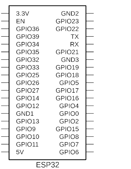
Pin Configuration and Descriptions

The ESP32 has a flexible pinout, with many pins serving multiple functions. Below is a table of commonly used pins and their descriptions:

Pin Name Function(s) Description
GPIO0 Input, Output, Boot Mode Used for boot mode selection during startup
GPIO2 Input, Output, ADC, PWM General-purpose pin with ADC and PWM support
GPIO4 Input, Output, ADC, PWM General-purpose pin with ADC and PWM support
GPIO5 Input, Output, ADC, PWM General-purpose pin with ADC and PWM support
GPIO12 Input, Output, ADC, PWM General-purpose pin with ADC and PWM support
GPIO13 Input, Output, ADC, PWM General-purpose pin with ADC and PWM support
GPIO14 Input, Output, ADC, PWM General-purpose pin with ADC and PWM support
GPIO15 Input, Output, ADC, PWM General-purpose pin with ADC and PWM support
GPIO16 Input, Output General-purpose pin
GPIO17 Input, Output General-purpose pin
EN Enable Chip enable pin; active high
VIN Power Input Input voltage (5V)
GND Ground Ground connection

Note: The exact pinout may vary depending on the ESP32 module or development board being used (e.g., ESP32-WROOM-32, ESP32-WROVER).

Usage Instructions

The ESP32 can be used in a variety of circuits and applications. Below are the steps and best practices for using the ESP32 in your projects:

Basic Setup

  1. Power Supply: Ensure the ESP32 is powered with a stable voltage between 3.0V and 3.6V. If using a development board, you can supply 5V via the VIN pin or USB.
  2. Programming Environment: Install the Arduino IDE or ESP-IDF (Espressif IoT Development Framework) for programming the ESP32.
  3. Connections:
    • Connect the EN pin to a pull-up resistor (if not already integrated).
    • Use GPIO0 for boot mode selection during firmware flashing.

Example: Blinking an LED with Arduino IDE

Below is an example of how to blink an LED connected to GPIO2 using the Arduino IDE:

// Define the GPIO pin where the LED is connected
#define LED_PIN 2

void setup() {
  // Set the LED pin as an output
  pinMode(LED_PIN, OUTPUT);
}

void loop() {
  // Turn the LED on
  digitalWrite(LED_PIN, HIGH);
  delay(1000); // Wait for 1 second

  // Turn the LED off
  digitalWrite(LED_PIN, LOW);
  delay(1000); // Wait for 1 second
}

Important Considerations

  • Boot Mode: Ensure GPIO0 is pulled low during firmware flashing and high during normal operation.
  • Voltage Levels: The ESP32 operates at 3.3V logic levels. Use level shifters if interfacing with 5V devices.
  • Antenna Placement: For optimal Wi-Fi and Bluetooth performance, ensure the onboard antenna is not obstructed by metal or other conductive materials.

Troubleshooting and FAQs

Common Issues and Solutions

  1. ESP32 Not Detected by Computer:

    • Ensure the correct USB driver is installed (e.g., CP2102 or CH340, depending on the board).
    • Check the USB cable for data transfer capability (some cables are power-only).
  2. Failed to Upload Code:

    • Verify that GPIO0 is pulled low during flashing.
    • Check the COM port and board settings in the Arduino IDE or ESP-IDF.
  3. Wi-Fi Connection Issues:

    • Ensure the correct SSID and password are used in your code.
    • Check for interference or weak signal strength.
  4. Overheating:

    • Verify that the ESP32 is not drawing excessive current.
    • Use proper heat dissipation techniques if operating in high-power modes.

FAQs

Q: Can the ESP32 operate on battery power?
A: Yes, the ESP32 supports ultra-low power modes, making it suitable for battery-powered applications.

Q: How do I reset the ESP32?
A: Press the reset button on the development board or toggle the EN pin.

Q: Can I use the ESP32 with 5V logic devices?
A: No, the ESP32 operates at 3.3V logic levels. Use level shifters for compatibility with 5V devices.

Q: What is the maximum range of the ESP32's Wi-Fi?
A: The range depends on environmental factors but typically extends up to 100 meters in open space.

By following this documentation, you can effectively integrate the ESP32 into your projects and troubleshoot common issues.