How to Use NodeMCU ESP32: Examples, Pinouts, and Specs
Introduction
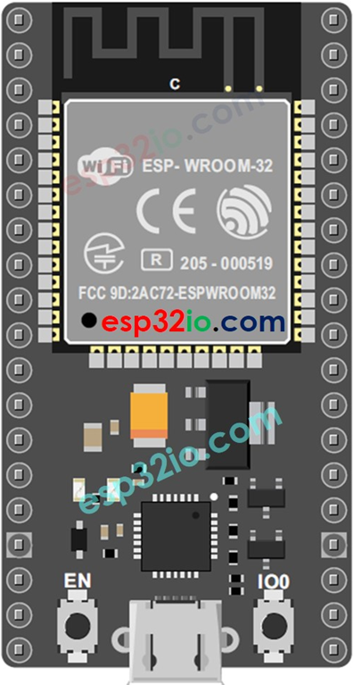
The NodeMCU ESP32 is a low-cost, open-source IoT platform based on the ESP32 microcontroller, developed by Espressif. It features integrated Wi-Fi and Bluetooth capabilities, making it an ideal choice for building connected devices and applications. The ESP32 is a powerful microcontroller with dual-core processing, a wide range of GPIO pins, and support for various communication protocols, making it versatile for IoT, home automation, and embedded systems projects.
Explore Projects Built with NodeMCU ESP32
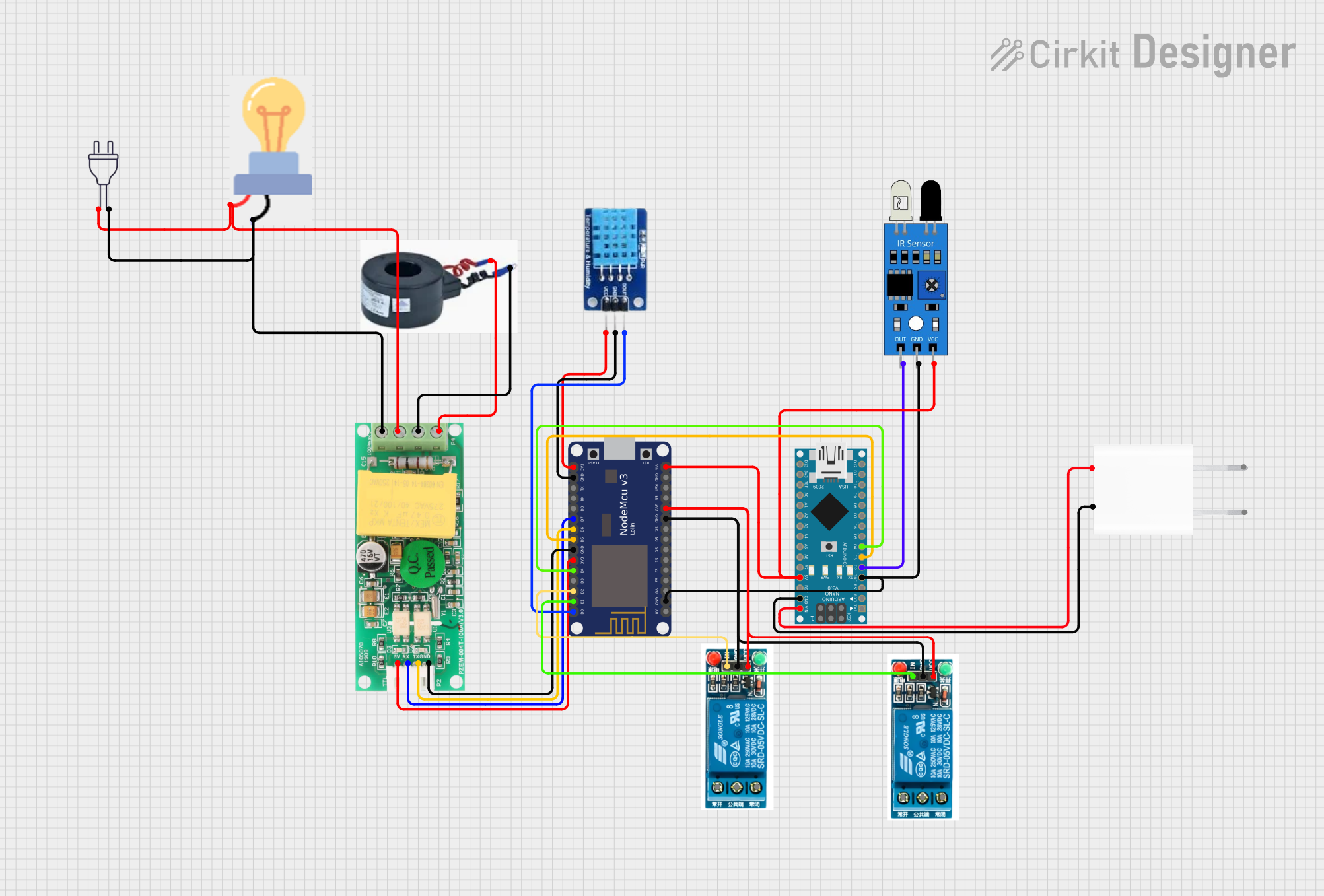
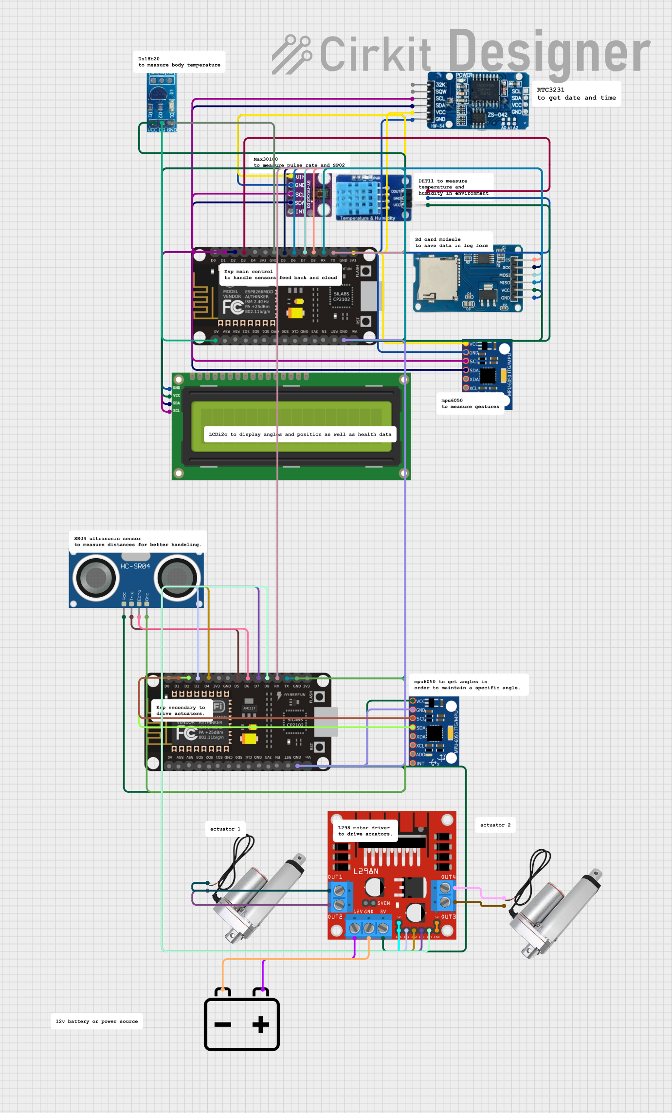
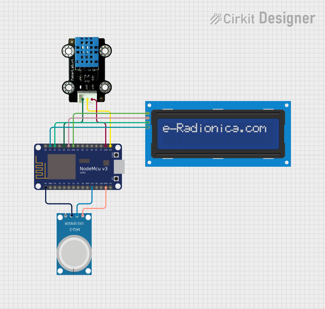
Explore Projects Built with NodeMCU ESP32
Common Applications and Use Cases
- IoT devices and smart home systems
- Wireless sensor networks
- Wearable technology
- Robotics and automation
- Data logging and remote monitoring
- Prototyping and educational projects
Technical Specifications
The NodeMCU ESP32 is packed with features that make it suitable for a wide range of applications. Below are its key technical specifications:
Key Technical Details
- Microcontroller: ESP32 (dual-core Xtensa LX6 processor)
- Clock Speed: Up to 240 MHz
- Flash Memory: 4 MB (varies by model)
- SRAM: 520 KB
- Wi-Fi: 802.11 b/g/n
- Bluetooth: v4.2 BR/EDR and BLE
- Operating Voltage: 3.3V
- Input Voltage: 5V (via USB) or 7-12V (via VIN pin)
- GPIO Pins: 30+ (multipurpose, including ADC, DAC, PWM, I2C, SPI, UART)
- ADC Resolution: 12-bit
- DAC Resolution: 8-bit
- Power Consumption: Ultra-low power consumption in deep sleep mode (~10 µA)
- Operating Temperature: -40°C to 125°C
Pin Configuration and Descriptions
The NodeMCU ESP32 has a variety of pins for different functionalities. Below is a table summarizing the key pins and their descriptions:
| Pin Name | Function | Description |
|---|---|---|
| VIN | Power Input | Accepts 7-12V input to power the board. |
| 3V3 | 3.3V Output | Provides 3.3V output for external components. |
| GND | Ground | Common ground for the circuit. |
| EN | Enable | Enables or disables the chip (active high). |
| IO0 | GPIO0 | General-purpose I/O pin, also used for boot mode selection. |
| IO2 | GPIO2 | General-purpose I/O pin, often used for onboard LED. |
| IO12-IO39 | GPIO Pins | Multipurpose pins for ADC, DAC, PWM, I2C, SPI, UART, etc. |
| TXD0, RXD0 | UART0 TX/RX | Default UART pins for serial communication. |
| SCL, SDA | I2C Clock and Data | Pins for I2C communication (default: GPIO22 and GPIO21). |
| MOSI, MISO, SCK | SPI Pins | Pins for SPI communication (default: GPIO23, GPIO19, GPIO18). |
| A0-A5 | Analog Input | ADC pins for analog-to-digital conversion. |
| BOOT | Boot Mode Selection | Used to enter bootloader mode for flashing firmware. |
Usage Instructions
The NodeMCU ESP32 is easy to use and can be programmed using the Arduino IDE or Espressif's ESP-IDF framework. Below are the steps to get started and important considerations:
How to Use the NodeMCU ESP32 in a Circuit
Powering the Board:
- Connect the board to your computer via a micro-USB cable for power and programming.
- Alternatively, supply 7-12V to the VIN pin or 3.3V to the 3V3 pin.
Programming the Board:
- Install the ESP32 board package in the Arduino IDE or use the ESP-IDF framework.
- Select the correct board and port in the IDE.
- Write your code and upload it to the board.
Connecting Peripherals:
- Use the GPIO pins to connect sensors, actuators, or other peripherals.
- Ensure the voltage levels of connected devices are compatible with the 3.3V logic of the ESP32.
Using Wi-Fi and Bluetooth:
- Use the built-in libraries (e.g.,
WiFi.handBluetoothSerial.h) to enable wireless communication.
- Use the built-in libraries (e.g.,
Important Considerations and Best Practices
- Voltage Levels: The GPIO pins operate at 3.3V. Avoid connecting 5V devices directly to the pins without a level shifter.
- Power Supply: Ensure a stable power supply, especially when using Wi-Fi or Bluetooth, as these features can draw significant current.
- Deep Sleep Mode: Use deep sleep mode to conserve power in battery-powered applications.
- Boot Mode: If the board does not enter programming mode, press and hold the BOOT button while uploading the code.
Example Code for Arduino IDE
Below is an example of how to connect the NodeMCU ESP32 to a Wi-Fi network and blink an LED:
#include <WiFi.h> // Include the Wi-Fi library

// Replace with your network credentials
const char* ssid = "Your_SSID";
const char* password = "Your_PASSWORD";

const int ledPin = 2; // GPIO2 is often connected to the onboard LED

void setup() {
  pinMode(ledPin, OUTPUT); // Set the LED pin as an output
  Serial.begin(115200);    // Start the serial communication

  // Connect to Wi-Fi
  Serial.print("Connecting to Wi-Fi");
  WiFi.begin(ssid, password);
  while (WiFi.status() != WL_CONNECTED) {
    delay(500);
    Serial.print(".");
  }
  Serial.println("\nWi-Fi connected!");
  Serial.print("IP Address: ");
  Serial.println(WiFi.localIP()); // Print the device's IP address
}

void loop() {
  digitalWrite(ledPin, HIGH); // Turn the LED on
  delay(1000);                // Wait for 1 second
  digitalWrite(ledPin, LOW);  // Turn the LED off
  delay(1000);                // Wait for 1 second
}
Troubleshooting and FAQs
Common Issues and Solutions
Problem: The board is not detected by the computer.
Solution:- Ensure the USB cable is functional and supports data transfer.
- Install the correct USB-to-serial driver for the ESP32.
Problem: Code upload fails with a timeout error.
Solution:- Press and hold the BOOT button while uploading the code.
- Check that the correct board and port are selected in the IDE.
Problem: Wi-Fi connection fails.
Solution:- Double-check the SSID and password.
- Ensure the Wi-Fi network is within range and supports 2.4 GHz (ESP32 does not support 5 GHz).
Problem: GPIO pins are not functioning as expected.
Solution:- Verify the pin mode is correctly set in the code.
- Check for conflicts with other peripherals or functions.
FAQs
Q: Can the NodeMCU ESP32 be powered by a battery?
A: Yes, it can be powered using a 3.7V LiPo battery connected to the VIN pin with a suitable regulator.Q: How do I reset the board?
A: Press the EN (Enable) button to reset the board.Q: Can I use the ESP32 with 5V logic devices?
A: No, the ESP32 operates at 3.3V logic. Use a level shifter for 5V devices.Q: What is the maximum number of GPIO pins I can use?
A: The ESP32 has over 30 GPIO pins, but some are reserved for specific functions. Refer to the datasheet for details.