How to Use Relay 2pcs: Examples, Pinouts, and Specs
Introduction
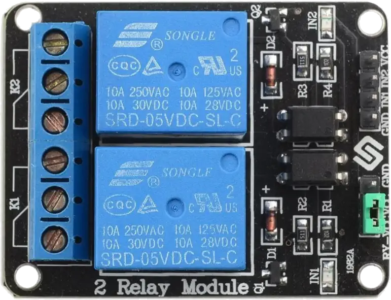
A relay is an electromechanical switch that uses an electromagnetic coil to open or close contacts, enabling control of a high-power circuit with a low-power signal. This package includes two relays, making it ideal for projects requiring multiple switching mechanisms. Relays are widely used in automation, home appliances, automotive systems, and industrial control applications.
Explore Projects Built with Relay 2pcs


Explore Projects Built with Relay 2pcs
Common Applications:
- Home automation (e.g., controlling lights or appliances)
- Motor control in robotics
- Automotive systems (e.g., headlights, horns)
- Industrial machinery
- Signal isolation between high-power and low-power circuits
Technical Specifications
Below are the key technical details for the relays included in this package:
General Specifications:
- Type: Electromechanical relay
- Coil Voltage: 5V DC
- Switching Voltage: Up to 250V AC or 30V DC
- Switching Current: Up to 10A
- Contact Configuration: SPDT (Single Pole Double Throw)
- Insulation Resistance: ≥ 100MΩ at 500V DC
- Operating Temperature: -40°C to +85°C
- Dimensions: 19mm x 15mm x 15mm (per relay)
Pin Configuration:
Each relay has 5 pins, as described in the table below:
| Pin Number | Name | Description |
|---|---|---|
| 1 | Coil (+) | Positive terminal of the electromagnetic coil (connect to 5V DC). |
| 2 | Coil (-) | Negative terminal of the electromagnetic coil (connect to ground). |
| 3 | Common (COM) | Common terminal for the switching mechanism. |
| 4 | Normally Open (NO) | Open circuit when the relay is inactive; closes when the relay is activated. |
| 5 | Normally Closed (NC) | Closed circuit when the relay is inactive; opens when the relay is activated. |
Usage Instructions
How to Use the Relay in a Circuit:
- Power the Coil: Connect the coil pins (1 and 2) to a 5V DC power source. Use a transistor or microcontroller to control the coil activation.
- Connect the Load:
- Connect the high-power circuit to the Common (COM) pin (Pin 3).
- Use the Normally Open (NO) pin (Pin 4) if you want the circuit to close only when the relay is activated.
- Use the Normally Closed (NC) pin (Pin 5) if you want the circuit to remain closed until the relay is activated.
- Control the Relay: Use a low-power signal (e.g., from an Arduino or other microcontroller) to activate the relay coil, which will switch the high-power circuit.
Important Considerations:
- Flyback Diode: Always connect a flyback diode across the coil terminals to protect your circuit from voltage spikes when the relay is deactivated.
- Isolation: Ensure proper isolation between the low-power control circuit and the high-power load to prevent damage.
- Current Ratings: Do not exceed the relay's maximum current and voltage ratings to avoid overheating or failure.
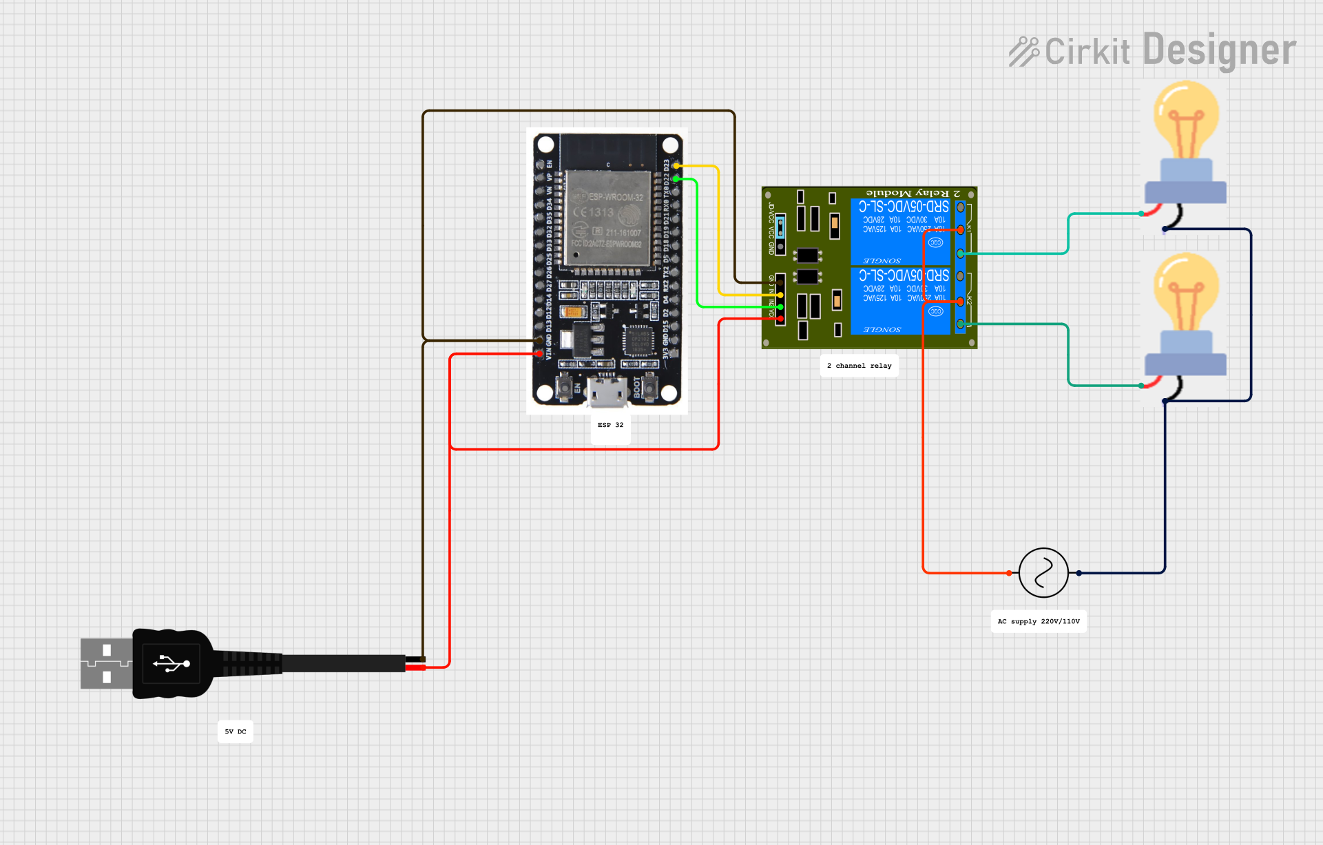
Example: Connecting a Relay to an Arduino UNO
Below is an example of how to control a relay using an Arduino UNO:
Circuit Connections:
- Connect the relay's Coil (+) pin to a digital pin on the Arduino (e.g., Pin 7) through a 1kΩ resistor.
- Connect the Coil (-) pin to the Arduino's GND.
- Connect the Common (COM) pin to one terminal of the load (e.g., a light bulb).
- Connect the Normally Open (NO) pin to the power source for the load.
Arduino Code:
// Define the relay pin
const int relayPin = 7;

void setup() {
  pinMode(relayPin, OUTPUT); // Set the relay pin as an output
  digitalWrite(relayPin, LOW); // Ensure the relay is off at startup
}

void loop() {
  digitalWrite(relayPin, HIGH); // Activate the relay
  delay(1000); // Keep the relay on for 1 second
  digitalWrite(relayPin, LOW); // Deactivate the relay
  delay(1000); // Keep the relay off for 1 second
}
Best Practices:
- Use a transistor (e.g., 2N2222) or a relay driver module to control the relay if the microcontroller cannot supply sufficient current.
- Avoid switching inductive loads (e.g., motors) without proper snubber circuits to suppress voltage spikes.
Troubleshooting and FAQs
Common Issues:
Relay Not Activating:
- Cause: Insufficient voltage or current to the coil.
- Solution: Verify the power supply and ensure the control signal is sufficient.
Relay Stuck in One State:
- Cause: Damaged contacts due to overcurrent or arcing.
- Solution: Replace the relay and ensure the load does not exceed the rated current.
Voltage Spikes Damaging the Circuit:
- Cause: Lack of a flyback diode across the coil.
- Solution: Install a flyback diode (e.g., 1N4007) across the coil terminals.
Excessive Heat:
- Cause: Overloading the relay or poor ventilation.
- Solution: Reduce the load or improve airflow around the relay.
FAQs:
Q: Can I use this relay with a 3.3V microcontroller?
A: Yes, but you will need a transistor or relay driver circuit to step up the control voltage to 5V.Q: Can this relay switch DC motors?
A: Yes, but ensure the motor's current and voltage are within the relay's ratings. Use a snubber circuit to suppress voltage spikes.Q: How do I know if the relay is working?
A: You should hear a clicking sound when the relay switches. You can also measure continuity between the COM and NO/NC pins.
By following this documentation, you can effectively use the Relay 2pcs in your projects for reliable and efficient switching.