How to Use Adafruit 8x16 LED Matrix FeatherWing - White: Examples, Pinouts, and Specs
Introduction
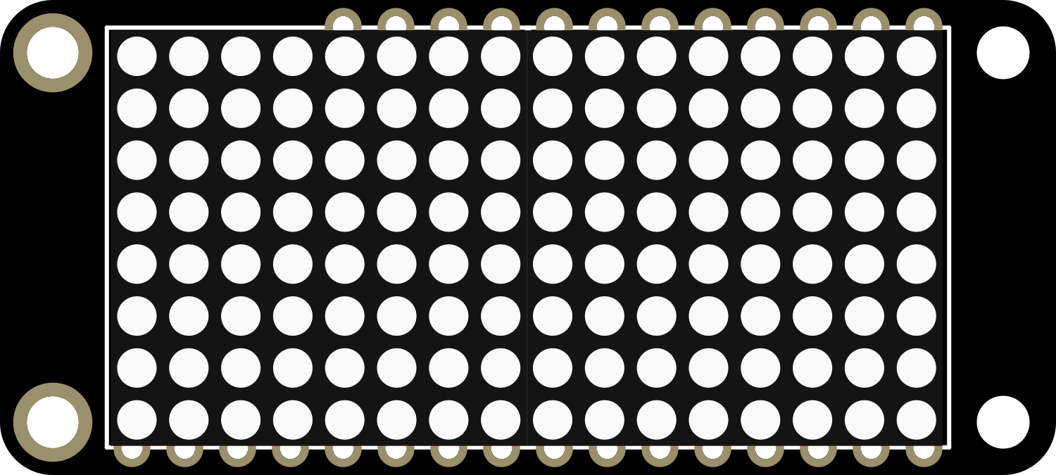
The Adafruit 8x16 LED Matrix FeatherWing in White is a versatile and visually striking electronic component that provides a grid of 8x16 white LEDs. This LED matrix is designed to be used with the Adafruit Feather series of development boards, enabling hobbyists and professionals alike to create projects with scrolling text, animations, and simple graphics. It is an ideal choice for wearable electronics, custom displays, and interactive art installations.
Explore Projects Built with Adafruit 8x16 LED Matrix FeatherWing - White
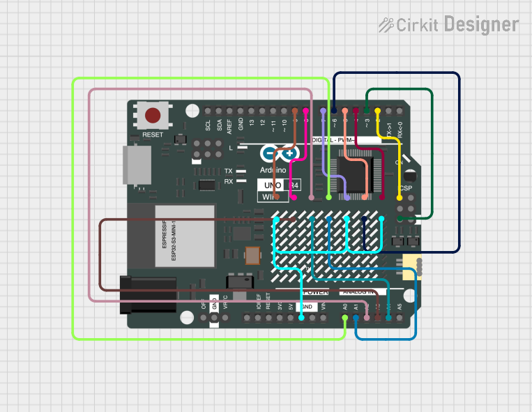


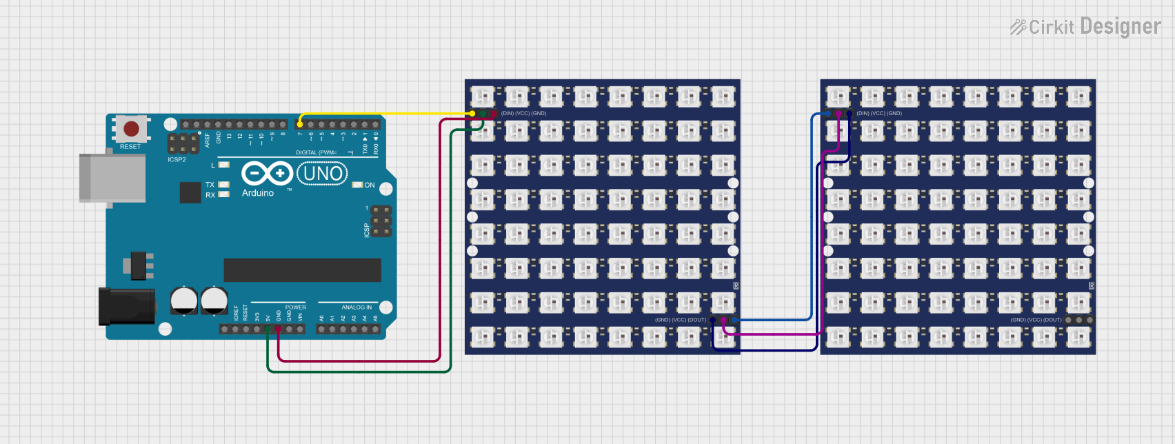
Explore Projects Built with Adafruit 8x16 LED Matrix FeatherWing - White
Common Applications and Use Cases
- Wearable electronic displays
- Custom message boards
- Interactive art installations
- Data visualization for sensors
- Educational tools for learning programming and electronics
Technical Specifications
Key Technical Details
- Operating Voltage: 3.3V to 5V
- Max Current (all LEDs on): 400mA
- LED Color: White
- Matrix Size: 8x16 LEDs
- Dimensions: 51mm x 23mm x 2.5mm
- Weight: 4.7 grams
Pin Configuration and Descriptions
| Pin | Function | Description |
|---|---|---|
| GND | Ground | Common ground for power and logic |
| 3V | Power | 3.3V power supply input |
| SDA | Data | I2C data line |
| SCL | Clock | I2C clock line |
| RST | Reset | Reset pin (optional use) |
Usage Instructions
How to Use the Component in a Circuit
- Powering the Matrix: Connect the 3V and GND pins to the corresponding power supply pins on your Feather board.
- Data Connection: Connect the SDA and SCL pins to the I2C data and clock lines on your Feather board.
- Software Library: Install the Adafruit LED Backpack library using the Arduino Library Manager.
- Initialization: In your code, create an object of the matrix display class provided by the library.
- Displaying Text/Graphics: Use the library functions to display text or graphics on the LED matrix.
Important Considerations and Best Practices
- Ensure that the power supply can handle the maximum current draw when all LEDs are on.
- Use I2C pull-up resistors if your Feather board does not have them built-in.
- Avoid looking directly at the LEDs for extended periods to prevent eye strain.
- When designing enclosures, ensure adequate ventilation to prevent overheating.
Example Code for Arduino UNO
#include <Wire.h>
#include <Adafruit_GFX.h>
#include <Adafruit_LEDBackpack.h>

Adafruit_8x16matrix matrix = Adafruit_8x16matrix();

void setup() {
  matrix.begin(0x70); // Initialize the matrix with the I2C address
  matrix.setBrightness(10); // Set brightness level (0 is dim, 15 is bright)
}

void loop() {
  matrix.clear(); // Clear the matrix display
  matrix.setCursor(0, 0); // Set cursor at top-left corner
  matrix.print("Hello"); // Print a message to the matrix
  matrix.writeDisplay(); // Update the display with the new data
  delay(2000); // Wait for 2 seconds
}
Note: The above code is for illustration purposes. You will need to adjust the I2C address (0x70) if you have changed the default address or if you are using multiple LED matrices on the same I2C bus.
Troubleshooting and FAQs
Common Issues Users Might Face
- LEDs Not Lighting Up: Check the power connections and ensure the matrix is properly powered.
- Garbled Display: Verify that the I2C connections are secure and that there are no shorts.
- Dim Display: Adjust the brightness setting in your code or check the power supply.
Solutions and Tips for Troubleshooting
- Double-check wiring against the pin configuration table.
- Ensure that the Adafruit LED Backpack library is correctly installed.
- Restart the Feather board and re-upload the code if changes are not taking effect.
- If using multiple devices on the I2C bus, ensure each device has a unique address.
FAQs
Q: Can I use this LED matrix with other microcontrollers besides the Feather series?
A: Yes, as long as the microcontroller supports I2C communication and can provide the necessary power requirements.
Q: How do I change the I2C address of the matrix?
A: The I2C address can be changed by soldering the address jumpers on the back of the PCB. Refer to the Adafruit guide for detailed instructions.
Q: Is it possible to chain multiple matrices together?
A: Yes, multiple LED matrices can be chained together by connecting their I2C lines in parallel and assigning unique addresses to each matrix.
Q: Can I display images on the matrix?
A: Yes, you can display bitmap images, but they need to be monochrome and formatted to fit the 8x16 resolution of the matrix.
For further assistance, consult the Adafruit forums or the detailed product guides available on the Adafruit website.