How to Use 5PCS MAX3232 3.3V to 5V DB9 Male RS232 Serial Prot to TTL Converter: Examples, Pinouts, and Specs
Introduction
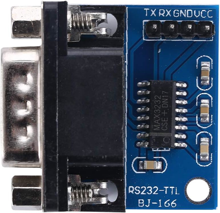
The 5PCS MAX3232 3.3V to 5V DB9 Male RS232 Serial Port to TTL Converter, manufactured by ANMBEST (Part ID: 922a517a-7ba9-4ba0-bc53-c116ec20841b), is a versatile module designed to bridge communication between RS232 serial devices and TTL logic levels. It converts RS232 signals (used in legacy serial communication) to TTL levels (used in modern microcontrollers) and supports both 3.3V and 5V systems. This makes it ideal for interfacing microcontrollers, such as Arduino, Raspberry Pi, or other embedded systems, with RS232-enabled devices like PCs, modems, or industrial equipment.
Explore Projects Built with 5PCS MAX3232 3.3V to 5V DB9 Male RS232 Serial Prot to TTL Converter
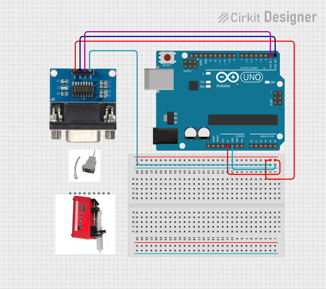


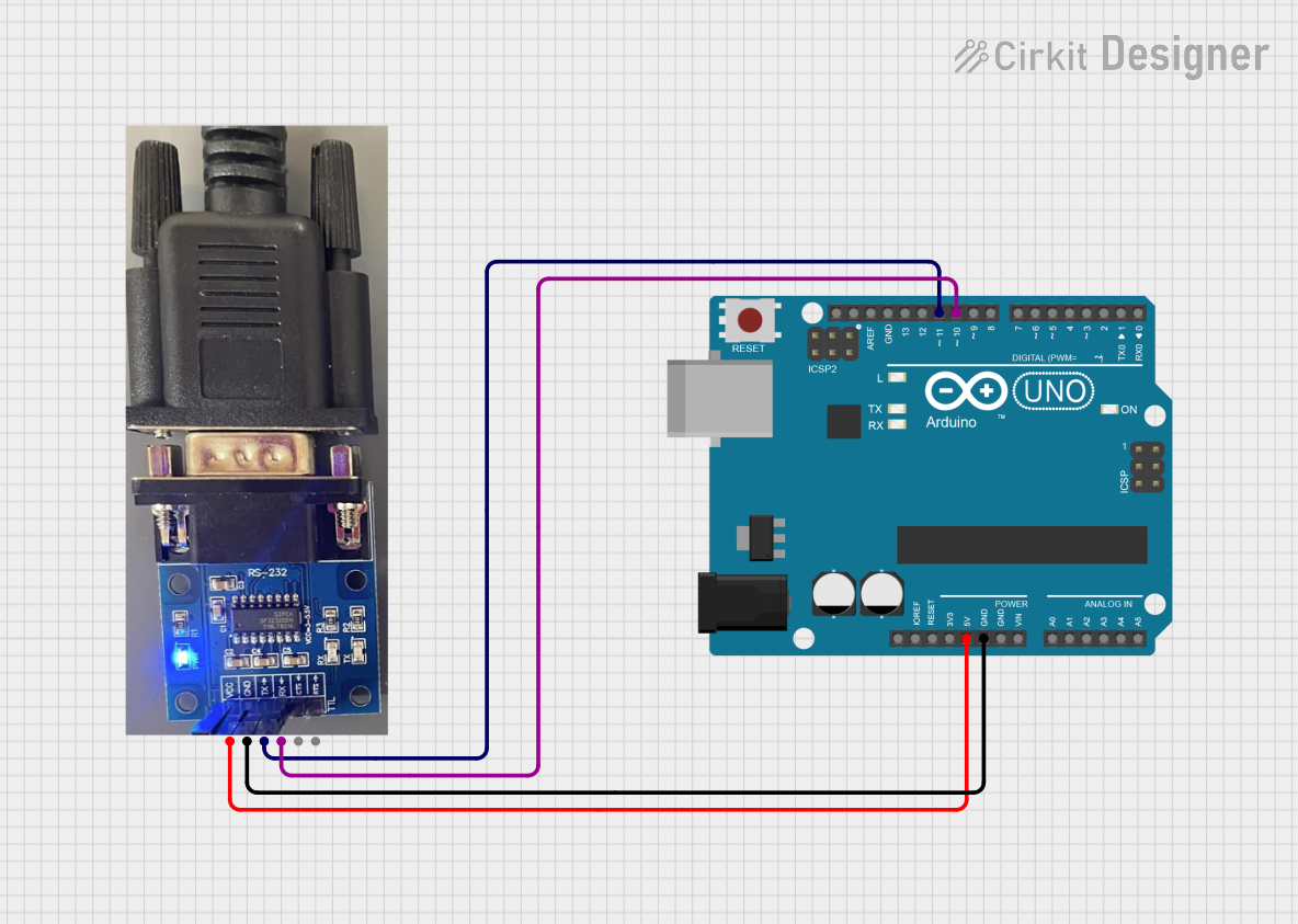
Explore Projects Built with 5PCS MAX3232 3.3V to 5V DB9 Male RS232 Serial Prot to TTL Converter
Common Applications and Use Cases
- Interfacing microcontrollers with RS232 devices.
- Debugging and programming embedded systems.
- Communication with legacy serial devices such as modems, printers, or industrial controllers.
- Serial communication in robotics and IoT projects.
- Data logging and monitoring applications.
Technical Specifications
Key Technical Details
- Chipset: MAX3232
- Voltage Levels: Supports both 3.3V and 5V systems.
- Communication Protocol: RS232 to TTL.
- Connector Type: DB9 Male for RS232 interface.
- Operating Voltage: 3.3V to 5V DC.
- Baud Rate: Up to 120 kbps.
- Dimensions: Compact PCB design for easy integration.
- Number of Units: 5 converters per set.
Pin Configuration and Descriptions
The module has two main interfaces: the DB9 Male connector for RS232 communication and a 4-pin TTL header for microcontroller interfacing.
DB9 Male Connector (RS232 Interface)
| Pin Number | Signal Name | Description |
|---|---|---|
| 2 | RXD | Receive Data (input to the module) |
| 3 | TXD | Transmit Data (output from module) |
| 5 | GND | Ground |
TTL Header (Microcontroller Interface)
| Pin Number | Signal Name | Description |
|---|---|---|
| 1 | VCC | Power input (3.3V or 5V) |
| 2 | GND | Ground |
| 3 | TXD | Transmit Data (output to MCU) |
| 4 | RXD | Receive Data (input from MCU) |
Usage Instructions
How to Use the Component in a Circuit
- Power the Module: Connect the
VCCpin to the 3.3V or 5V power supply of your microcontroller and theGNDpin to the ground. - Connect the TTL Interface:
- Connect the
TXDpin of the module to theRXpin of your microcontroller. - Connect the
RXDpin of the module to theTXpin of your microcontroller.
- Connect the
- Connect the RS232 Device: Plug the DB9 Male connector into the RS232 device (e.g., PC or modem).
- Verify Connections: Double-check all connections to ensure proper signal flow.
- Test Communication: Use a serial communication tool (e.g., Arduino Serial Monitor or a terminal emulator) to test data transmission and reception.
Important Considerations and Best Practices
- Ensure the module's
VCCmatches the logic level of your microcontroller (3.3V or 5V). - Use short and shielded cables for RS232 connections to minimize noise and signal degradation.
- Avoid hot-plugging the module to prevent damage to the circuitry.
- If using with an Arduino UNO, ensure the
Serialpins (0 and 1) are not used for other purposes during communication.
Example Code for Arduino UNO
Below is an example of how to use the MAX3232 module with an Arduino UNO to send and receive data via RS232.
// Example: Sending and receiving data via MAX3232 RS232 to TTL Converter
// Connect the module's TXD to Arduino RX (pin 0) and RXD to Arduino TX (pin 1)

void setup() {
  Serial.begin(9600); // Initialize serial communication at 9600 baud
  delay(1000); // Allow time for the module to initialize

  Serial.println("MAX3232 RS232 to TTL Converter Test");
  // Send a test message to the RS232 device
}

void loop() {
  // Check if data is available from the RS232 device
  if (Serial.available() > 0) {
    char receivedChar = Serial.read(); // Read the incoming character
    Serial.print("Received: "); // Print the received data to Serial Monitor
    Serial.println(receivedChar);
  }

  // Send a message to the RS232 device every 5 seconds
  delay(5000);
  Serial.println("Hello from Arduino!");
}
Troubleshooting and FAQs
Common Issues and Solutions
No Communication Between Devices:
- Cause: Incorrect wiring or mismatched baud rates.
- Solution: Verify the connections between the module and the microcontroller. Ensure the baud rate in your code matches the RS232 device's settings.
Data Corruption or Noise:
- Cause: Long or unshielded RS232 cables.
- Solution: Use shorter, shielded cables to reduce noise and signal degradation.
Module Not Powering On:
- Cause: Incorrect
VCCvoltage or loose connections. - Solution: Ensure the
VCCpin is connected to a stable 3.3V or 5V power source and theGNDpin is properly grounded.
- Cause: Incorrect
Hot-Plugging Damage:
- Cause: Connecting or disconnecting the module while powered.
- Solution: Always power off the system before connecting or disconnecting the module.
FAQs
Q1: Can this module work with 3.3V microcontrollers like ESP32 or Raspberry Pi?
A1: Yes, the MAX3232 supports both 3.3V and 5V logic levels, making it compatible with 3.3V microcontrollers.
Q2: What is the maximum cable length for RS232 communication?
A2: RS232 supports cable lengths up to 15 meters (50 feet) at lower baud rates. For higher baud rates, shorter cables are recommended.
Q3: Can I use this module for bidirectional communication?
A3: Yes, the module supports full-duplex communication, allowing simultaneous data transmission and reception.
Q4: Is this module compatible with USB-to-RS232 adapters?
A4: Yes, it can be used with USB-to-RS232 adapters for interfacing with modern PCs.
This documentation provides a comprehensive guide to using the 5PCS MAX3232 RS232 to TTL Converter. For further assistance, refer to the manufacturer's datasheet or contact ANMBEST support.