How to Use I2C to 0-10V V1.0 Module : Examples, Pinouts, and Specs
Introduction
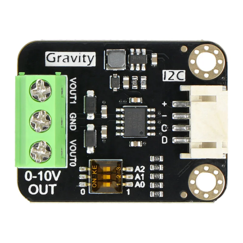
The I2C to 0-10V V1.0 Module is a versatile electronic component designed to convert I2C digital signals into a 0-10V analog output. This module enables microcontrollers, such as Arduino or Raspberry Pi, to interface seamlessly with analog devices like dimmers, motor controllers, and industrial equipment. It is particularly useful in applications requiring precise control of analog signals, such as lighting systems, HVAC systems, and process automation.
Explore Projects Built with I2C to 0-10V V1.0 Module
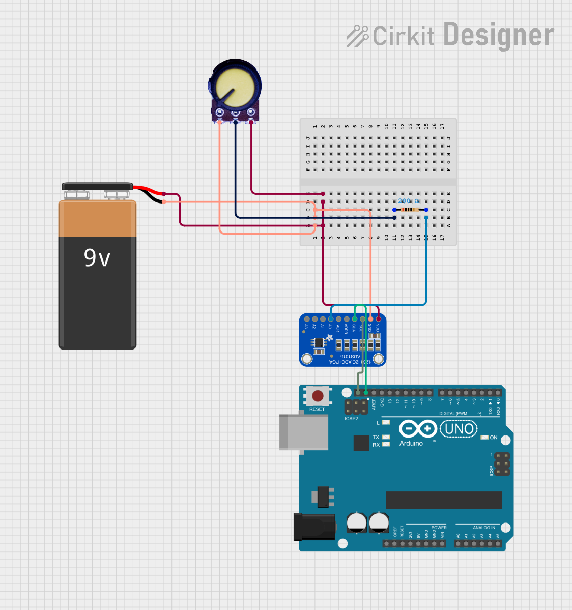
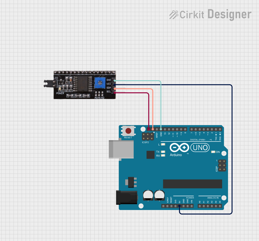
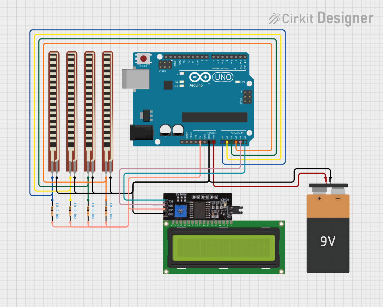
Explore Projects Built with I2C to 0-10V V1.0 Module
Technical Specifications
- Input Protocol: I2C (Inter-Integrated Circuit)
- Output Voltage Range: 0-10V DC
- Input Voltage (Vcc): 5V DC
- I2C Address: Configurable (default: 0x48)
- Output Current: Up to 10mA
- Resolution: 12-bit DAC (Digital-to-Analog Converter)
- Operating Temperature: -40°C to 85°C
- Dimensions: 25mm x 20mm x 10mm
Pin Configuration and Descriptions
| Pin Name | Description | Notes |
|---|---|---|
| VCC | Power supply input (5V DC) | Connect to the 5V pin of the MCU |
| GND | Ground | Common ground with the MCU |
| SDA | I2C data line | Connect to the SDA pin of the MCU |
| SCL | I2C clock line | Connect to the SCL pin of the MCU |
| OUT | 0-10V analog output | Connect to the analog device |
Usage Instructions
Connecting the Module
- Power Supply: Connect the
VCCpin to a 5V DC power source and theGNDpin to the ground of your microcontroller. - I2C Communication: Connect the
SDAandSCLpins to the corresponding I2C pins on your microcontroller. For Arduino UNO, these areA4(SDA) andA5(SCL). - Analog Output: Connect the
OUTpin to the input of the analog device you wish to control.
Important Considerations
- Ensure the I2C address of the module does not conflict with other devices on the same I2C bus. The default address is
0x48, but it can be changed if necessary (refer to the module's datasheet for address configuration). - The module's output current is limited to 10mA. If your analog device requires more current, use a buffer circuit or an external amplifier.
- Use pull-up resistors (typically 4.7kΩ) on the SDA and SCL lines if your microcontroller does not have internal pull-ups enabled.
Example Code for Arduino UNO
Below is an example of how to use the I2C to 0-10V V1.0 Module with an Arduino UNO to generate a 5V analog output.
#include <Wire.h> // Include the Wire library for I2C communication

#define MODULE_ADDRESS 0x48 // Default I2C address of the module

void setup() {
  Wire.begin(); // Initialize I2C communication
  Serial.begin(9600); // Initialize serial communication for debugging
}

void loop() {
  uint16_t analogValue = 2048; // Example: 50% of 12-bit range (0-4095)

  // Send the analog value to the module
  Wire.beginTransmission(MODULE_ADDRESS);
  Wire.write(analogValue >> 8); // Send the high byte
  Wire.write(analogValue & 0xFF); // Send the low byte
  Wire.endTransmission();

  Serial.println("Analog value sent: 5V equivalent");
  delay(1000); // Wait for 1 second before sending the next value
}
Explanation of the Code
- The
Wire.begin()function initializes the I2C communication. - The
Wire.beginTransmission()function starts communication with the module at the specified I2C address. - The 12-bit analog value is split into two bytes (high and low) and sent to the module.
- The example sends a value corresponding to 5V (50% of the 0-10V range) every second.
Troubleshooting and FAQs
Common Issues
No Output Voltage:
- Ensure the module is powered correctly (check the
VCCandGNDconnections). - Verify that the I2C address matches the one used in your code.
- Check the SDA and SCL connections for proper wiring.
- Ensure the module is powered correctly (check the
Incorrect Output Voltage:
- Confirm that the analog value sent to the module is within the 12-bit range (0-4095).
- Ensure there is no significant voltage drop due to long wires or high resistance.
I2C Communication Failure:
- Use pull-up resistors on the SDA and SCL lines if not already present.
- Check for address conflicts with other I2C devices on the same bus.
FAQs
Q: Can I use this module with a 3.3V microcontroller?
A: Yes, but you will need a level shifter to convert the 3.3V I2C signals to 5V.
Q: How do I change the I2C address of the module?
A: Refer to the module's datasheet for instructions on configuring the address using solder jumpers or DIP switches.
Q: What happens if my analog device requires more than 10mA?
A: Use an external amplifier or buffer circuit to drive higher current loads.
Q: Can I generate a negative voltage output?
A: No, this module only supports a 0-10V positive voltage range. For negative voltages, additional circuitry is required.