How to Use LM2931_FIXED: Examples, Pinouts, and Specs

Introduction
The LM2931_FIXED is a low dropout voltage regulator designed to maintain a stable output voltage despite variations in input voltage. It is particularly suitable for battery-powered devices due to its low quiescent current and ability to operate with very low input voltages. Common applications include automotive electronics, portable devices, and any low-voltage electronic circuit requiring a regulated power supply.
Explore Projects Built with LM2931_FIXED
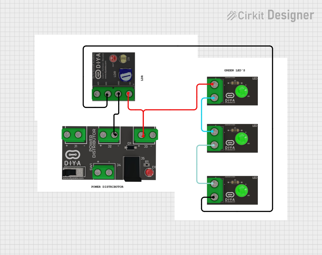
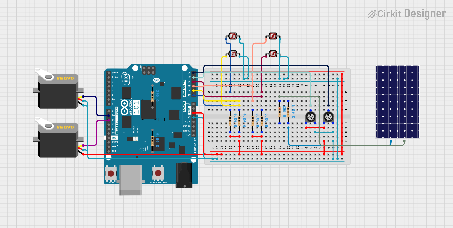
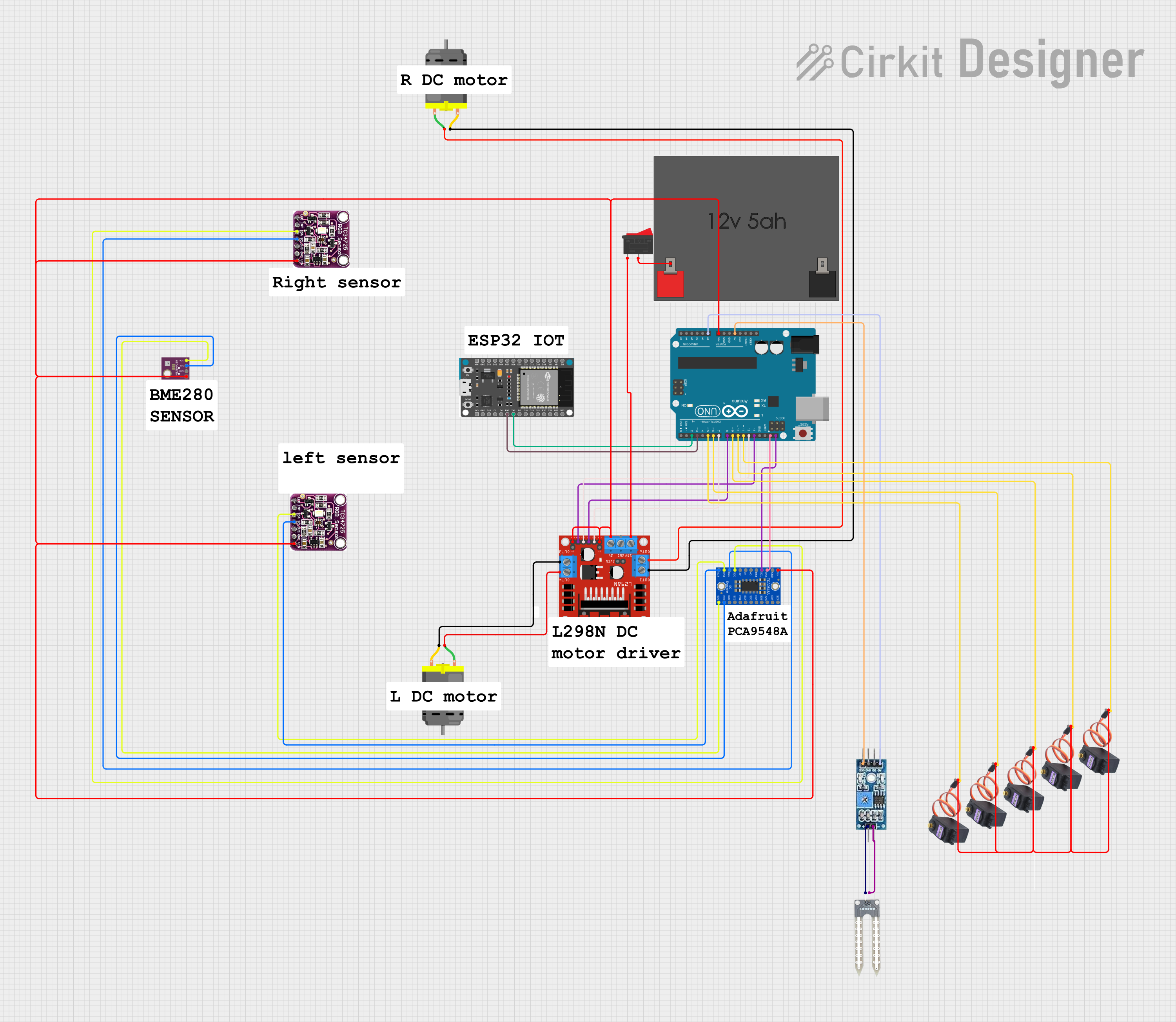
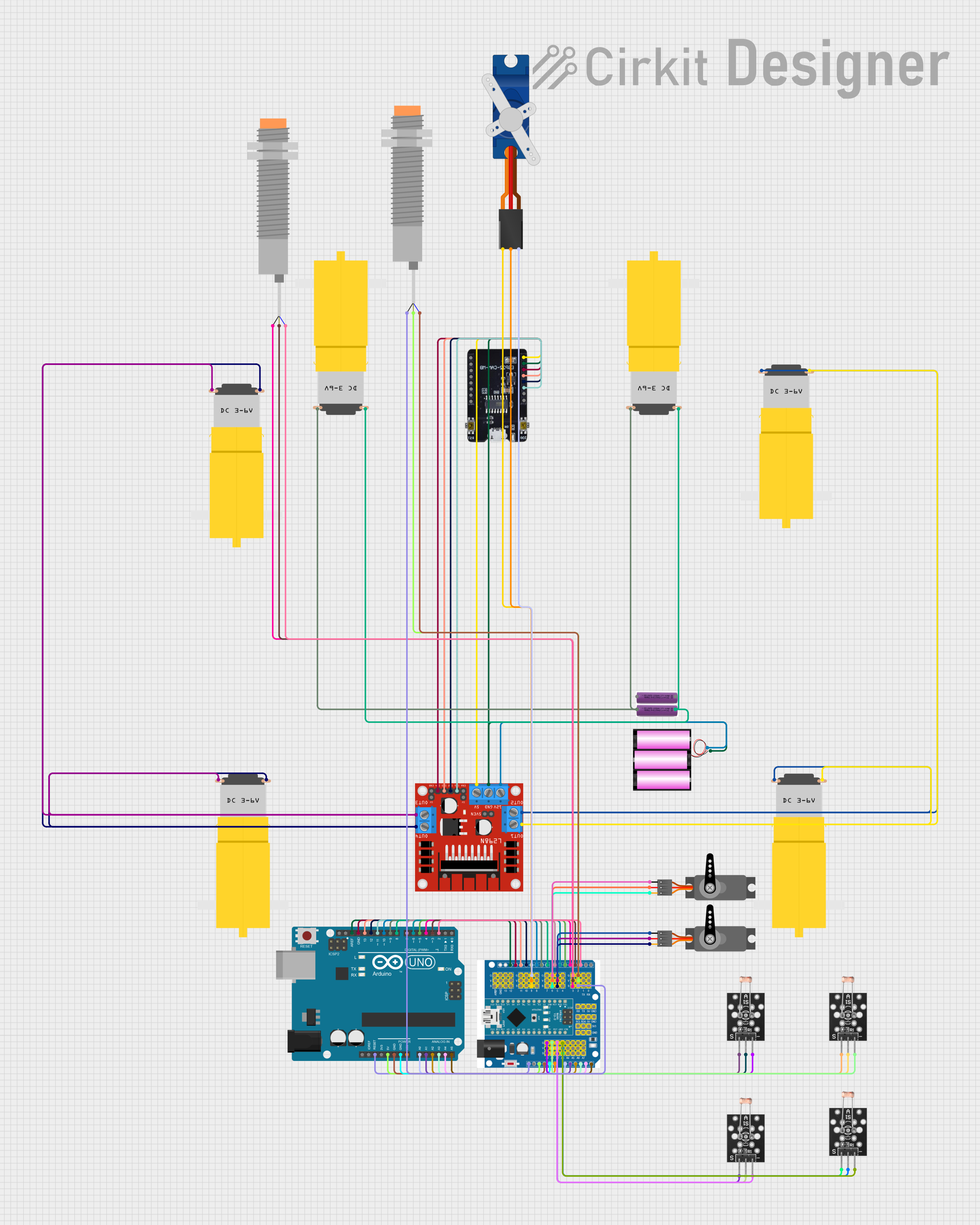
Explore Projects Built with LM2931_FIXED
Technical Specifications
Key Technical Details
- Output Voltage: Fixed (specify the exact voltage, e.g., 5V)
- Input Voltage Range: Typically 5.5V to 40V (verify with datasheet)
- Output Current: Up to 100mA
- Dropout Voltage: Typically 0.4V at 100mA load (verify with datasheet)
- Quiescent Current: Typically 1mA (verify with datasheet)
- Package: TO-92, TO-220, SOIC-8 (verify with datasheet)
Pin Configuration and Descriptions
| Pin Number | Name | Description |
|---|---|---|
| 1 | GND | Ground reference for the regulator. |
| 2 | OUT | Regulated output voltage. |
| 3 | IN | Unregulated input voltage. |
Usage Instructions
How to Use the LM2931_FIXED in a Circuit
Connecting the Input Voltage:
- Connect the unregulated input voltage to the IN pin (Pin 3).
- Ensure that the input voltage does not exceed the maximum rating specified in the datasheet.
Grounding:
- Connect the GND pin (Pin 1) to the ground plane of your circuit.
Output Voltage:
- The regulated output voltage can be drawn from the OUT pin (Pin 2).
- Add a decoupling capacitor (typically 1µF) between the OUT pin and GND close to the regulator to improve stability.
Important Considerations and Best Practices
Heat Dissipation:
- If the regulator is expected to dissipate significant power, consider using a heat sink.
- Calculate the power dissipation by multiplying the voltage drop across the regulator by the output current.
Input Capacitor:
- An input capacitor is not strictly necessary but is recommended to filter input noise. A value of 1µF should suffice.
Output Capacitor:
- The output capacitor improves transient response and should be placed as close to the regulator as possible.
Reverse Battery Protection:
- The LM2931_FIXED includes reverse battery protection, but it's still advisable to design your circuit with proper orientation in mind.
Bypassing the Dropout Voltage:
- Ensure that the input voltage is always at least the dropout voltage above the desired output voltage under all load conditions.
Troubleshooting and FAQs
Common Issues
Output Voltage is Too Low or Unstable:
- Check if the input voltage is at least the dropout voltage higher than the output voltage.
- Ensure that the output and input capacitors are properly installed.
Regulator Overheating:
- Verify that the current draw is within the specified limits.
- Consider improving heat dissipation with a heat sink or by increasing PCB copper area.
Solutions and Tips for Troubleshooting
No Output Voltage:
- Check for proper pin connections and solder joints.
- Ensure that the input voltage is present and within the specified range.
Fluctuating Output:
- Place the output capacitor as close to the regulator as possible.
- Check for any source of noise on the input side and add filtering if necessary.
FAQs
Q: Can I use the LM2931_FIXED without capacitors?
- A: While the LM2931_FIXED may work without capacitors, it's recommended to use them for optimal performance and stability.
Q: What is the maximum input voltage for the LM2931_FIXED?
- A: The maximum input voltage is typically 40V, but always verify with the datasheet for your specific part number.
Q: Is the LM2931_FIXED protected against reverse polarity?
- A: Yes, it includes reverse battery protection.
Example Connection with Arduino UNO
// Define the output voltage pin of the LM2931_FIXED
#define VOLTAGE_REG_OUT A0

void setup() {
  // Initialize the Serial Monitor at 9600 baud rate
  Serial.begin(9600);
}

void loop() {
  // Read the voltage from the regulator
  int sensorValue = analogRead(VOLTAGE_REG_OUT);
  // Convert the reading to voltage
  float voltage = sensorValue * (5.0 / 1023.0);
  // Print the voltage to the Serial Monitor
  Serial.println(voltage);
  // Wait for a second
  delay(1000);
}
Note: This code assumes that the fixed output voltage of the LM2931_FIXED is within the range that the Arduino's analog pin can measure (0-5V). If the output voltage is higher, a voltage divider or level shifting is required to bring the voltage within the measurable range.