How to Use Level shifter 3.3 to 5v: Examples, Pinouts, and Specs
Introduction
A level shifter is a circuit that enables communication between devices operating at different voltage levels, specifically converting signals from 3.3V logic to 5V logic and vice versa. This component is essential in mixed-voltage systems where devices with different logic levels need to interface seamlessly.
Explore Projects Built with Level shifter 3.3 to 5v


Explore Projects Built with Level shifter 3.3 to 5v
Common Applications and Use Cases
- Interfacing 3.3V microcontrollers (e.g., ESP32, Raspberry Pi) with 5V peripherals (e.g., sensors, displays).
- Bidirectional communication between I2C, SPI, or UART devices operating at different voltage levels.
- Voltage level translation in mixed-voltage systems for industrial and consumer electronics.
Technical Specifications
Key Technical Details
- Voltage Range (Low Side): 1.8V to 3.6V (typically 3.3V)
- Voltage Range (High Side): 4.5V to 5.5V (typically 5V)
- Maximum Data Rate: Up to 100 Mbps (depending on the specific IC or circuit design)
- Directionality: Bidirectional (automatic direction sensing)
- Operating Temperature Range: -40°C to +85°C
- Power Consumption: Typically low, depending on the load and data rate.
Pin Configuration and Descriptions
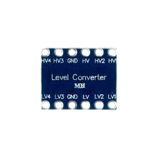
Below is a typical pinout for a 4-channel bidirectional level shifter module:
| Pin Name | Description |
|---|---|
| LV (Low Voltage) | Connect to the 3.3V (or lower) logic voltage source. |
| HV (High Voltage) | Connect to the 5V logic voltage source. |
| GND | Ground connection (common ground for both voltage levels). |
| LV1, LV2, LV3, LV4 | Low-voltage side data pins (connect to 3.3V logic device). |
| HV1, HV2, HV3, HV4 | High-voltage side data pins (connect to 5V logic device). |
Note: The number of channels (e.g., 4) may vary depending on the specific level shifter module.
Usage Instructions
How to Use the Component in a Circuit
Power Connections:
- Connect the
LVpin to the 3.3V power supply of the low-voltage device. - Connect the
HVpin to the 5V power supply of the high-voltage device. - Connect the
GNDpin to the common ground of both devices.
- Connect the
Signal Connections:
- Connect the low-voltage device's data lines to the
LVxpins. - Connect the high-voltage device's data lines to the corresponding
HVxpins.
- Connect the low-voltage device's data lines to the
Bidirectional Communication:
- The level shifter automatically detects the direction of data flow, so no additional configuration is required.
Important Considerations and Best Practices
- Ensure that the
LVandHVvoltage levels match the operating voltages of the connected devices. - Use pull-up resistors on I2C lines if the level shifter does not include them internally.
- Avoid exceeding the maximum data rate specified for the level shifter to prevent signal integrity issues.
- Keep the ground connections short and ensure a solid common ground between devices.
Example: Connecting to an Arduino UNO
Below is an example of using a level shifter to interface a 3.3V sensor with a 5V Arduino UNO:
Circuit Diagram
- Connect the sensor's 3.3V power pin to the
LVpin of the level shifter. - Connect the Arduino's 5V power pin to the
HVpin of the level shifter. - Connect the sensor's data pin to an
LVxpin, and the correspondingHVxpin to the Arduino's digital input pin.
Arduino Code Example
// Example: Reading data from a 3.3V sensor using a 5V Arduino UNO

const int sensorPin = 2; // Arduino pin connected to HVx of the level shifter
int sensorValue = 0;

void setup() {
  pinMode(sensorPin, INPUT); // Set the pin as input
  Serial.begin(9600);        // Initialize serial communication
}

void loop() {
  sensorValue = digitalRead(sensorPin); // Read the sensor value
  Serial.println(sensorValue);         // Print the value to the Serial Monitor
  delay(500);                          // Wait for 500ms before the next read
}
Note: Ensure the sensor's output is compatible with the level shifter's data rate and voltage levels.
Troubleshooting and FAQs
Common Issues and Solutions
No Signal Translation:
- Cause: Incorrect power connections.
- Solution: Verify that
LVandHVare connected to the correct voltage sources.
Data Corruption or Signal Loss:
- Cause: Exceeding the maximum data rate or using long wires.
- Solution: Reduce the data rate or shorten the wire lengths.
Unstable Communication:
- Cause: Missing pull-up resistors on I2C lines.
- Solution: Add appropriate pull-up resistors (e.g., 4.7kΩ) to the SDA and SCL lines.
Overheating:
- Cause: Excessive current draw or incorrect wiring.
- Solution: Check the wiring and ensure the connected devices are within the level shifter's specifications.
FAQs
Q1: Can I use this level shifter for SPI communication?
A1: Yes, the level shifter supports SPI communication. Ensure the data rate does not exceed the maximum supported by the level shifter.
Q2: Is this level shifter compatible with 1.8V logic devices?
A2: Yes, as long as the LV voltage is within the specified range (1.8V to 3.6V).
Q3: Do I need to configure the direction of data flow?
A3: No, the level shifter automatically detects the direction of data flow for bidirectional communication.
Q4: Can I use this level shifter for analog signals?
A4: No, this level shifter is designed for digital signals only. Use a dedicated analog level shifter for analog signals.
By following this documentation, you can effectively use a 3.3V to 5V level shifter in your projects to enable seamless communication between mixed-voltage devices.