How to Use HX711: Examples, Pinouts, and Specs
Introduction
The HX711 is a precision 24-bit analog-to-digital converter (ADC) designed specifically for weigh scales and industrial control applications. It features a built-in low-noise amplifier and a programmable gain, making it ideal for interfacing with load cells and other sensors requiring high accuracy and stability. The HX711 simplifies the process of converting small analog signals into digital data, enabling precise measurements in a wide range of applications.
Explore Projects Built with HX711
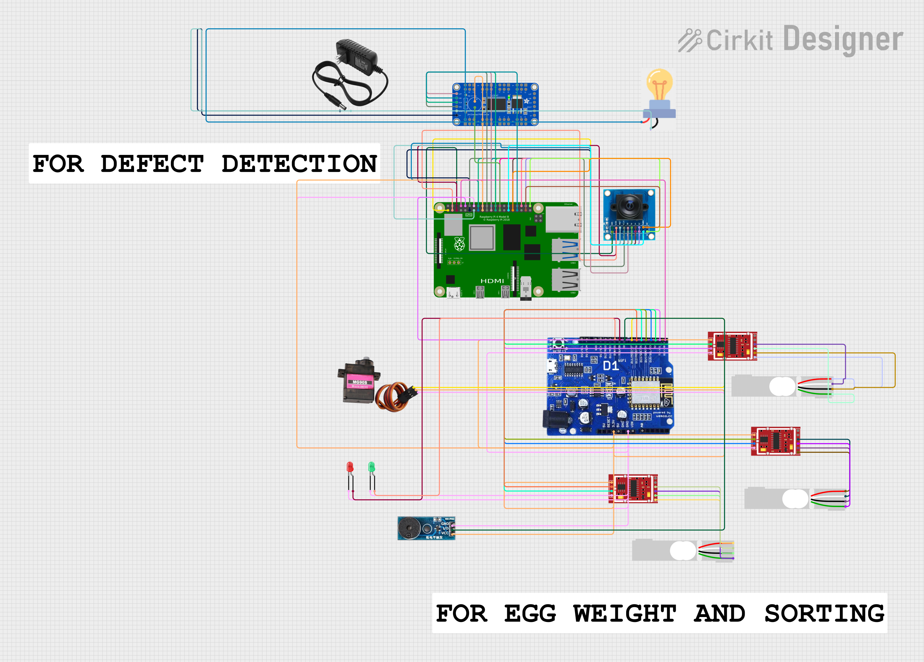
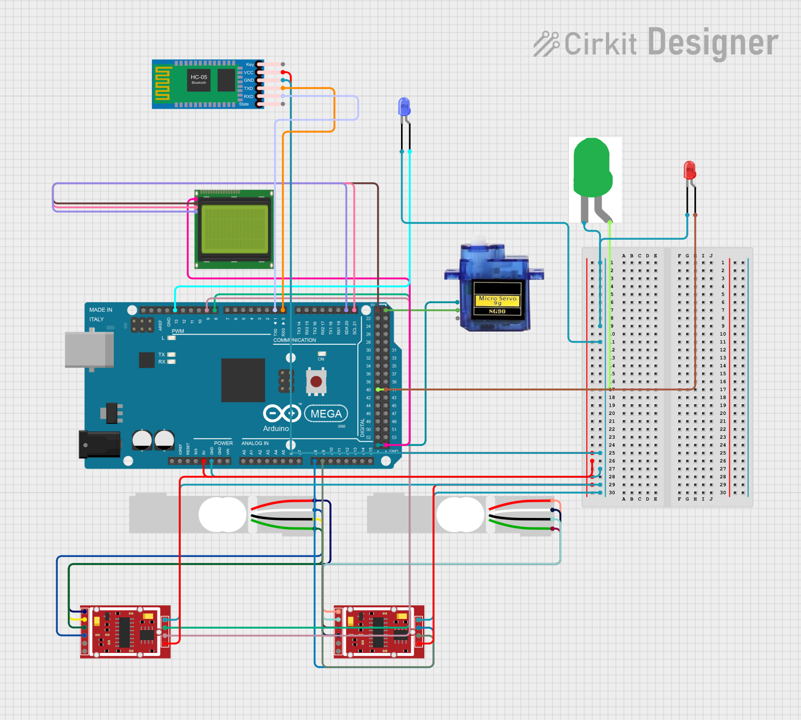

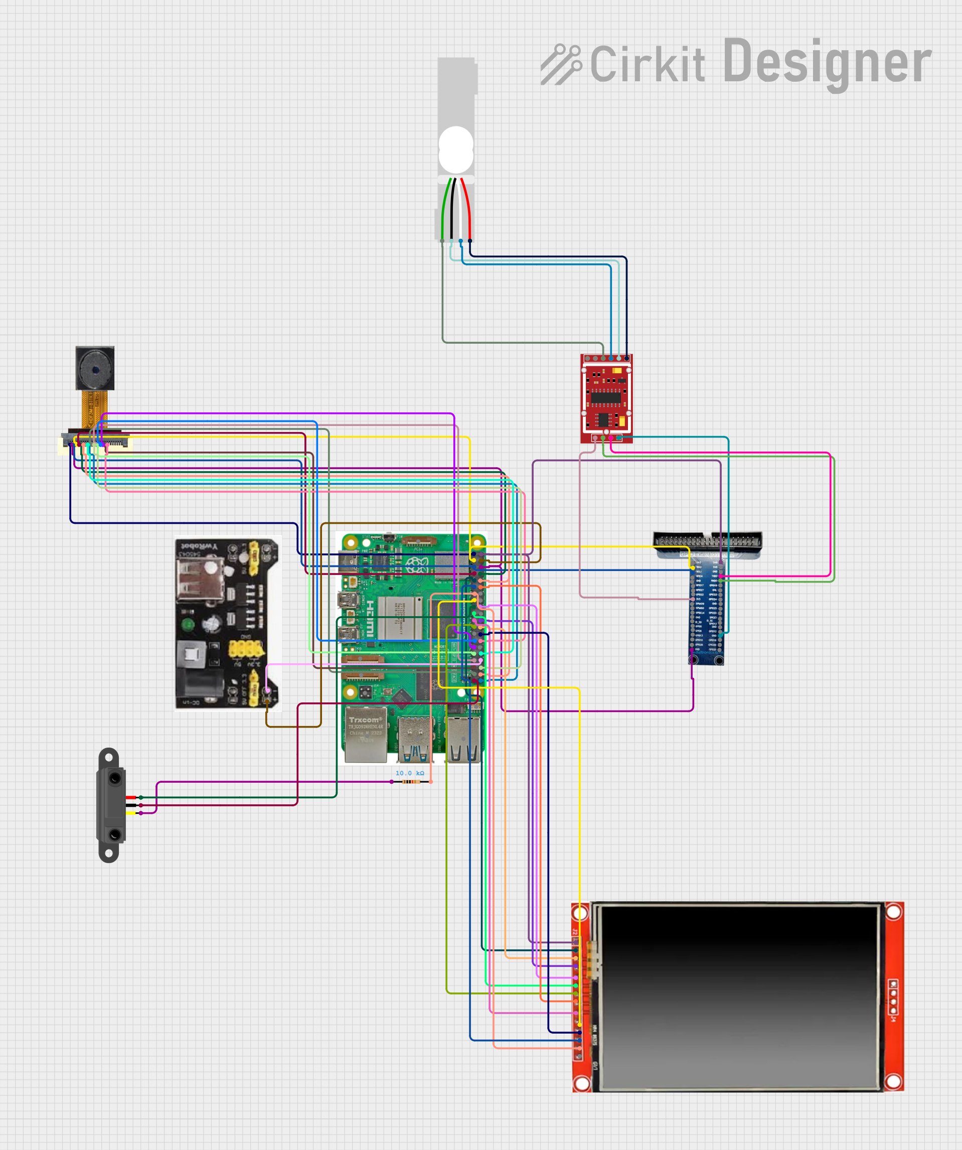
Explore Projects Built with HX711
Common Applications and Use Cases
- Digital weigh scales
- Industrial process control
- Load cell interfacing
- Force and pressure measurement systems
- IoT-based weight monitoring systems
Technical Specifications
The HX711 is a highly integrated ADC with the following key specifications:
| Parameter | Value |
|---|---|
| Supply Voltage | 2.6V to 5.5V |
| Operating Current | ~1.5mA |
| Standby Current | <1µA |
| Resolution | 24-bit |
| Input Channels | 2 (differential inputs) |
| Programmable Gain | 32, 64, or 128 |
| Data Rate | 10 Hz or 80 Hz |
| Temperature Range | -40°C to +85°C |
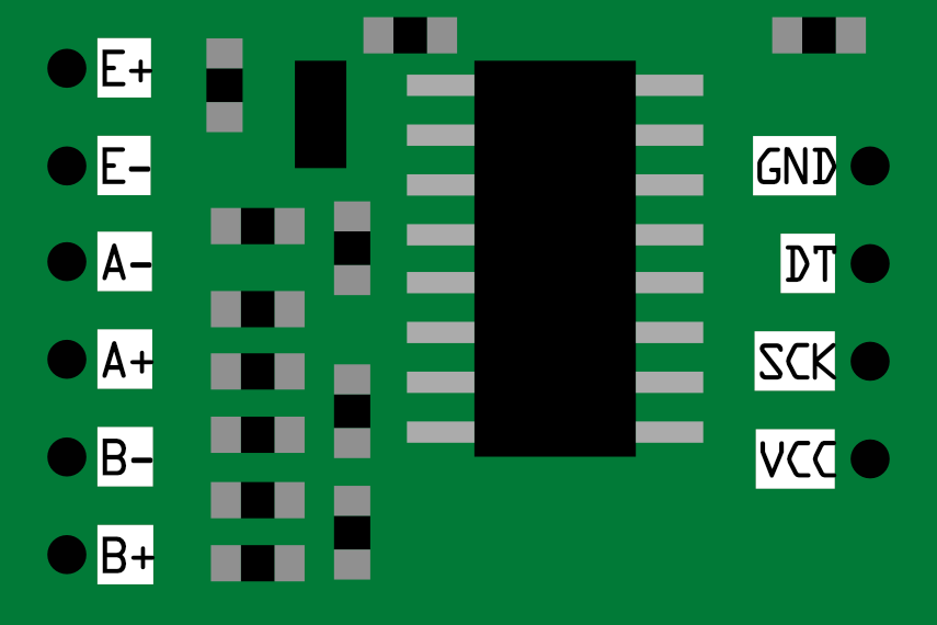
Pin Configuration and Descriptions
The HX711 has 16 pins, but the most commonly used package is the SOP-16. Below is the pin configuration:
| Pin | Name | Description |
|---|---|---|
| 1 | VCC | Power supply input (2.6V to 5.5V). |
| 2 | VFB | Feedback voltage for internal regulator (not commonly used). |
| 3 | BASE | Base voltage for internal regulator (not commonly used). |
| 4 | AVDD | Analog power supply (connect to VCC). |
| 5 | AGND | Analog ground. |
| 6 | BGND | Bridge ground (connect to AGND). |
| 7 | B- | Negative input for the bridge sensor (e.g., load cell). |
| 8 | B+ | Positive input for the bridge sensor (e.g., load cell). |
| 9 | VBG | Bridge voltage reference (not commonly used). |
| 10 | VOUT | Output voltage for internal regulator (not commonly used). |
| 11 | DGND | Digital ground. |
| 12 | PD_SCK | Power-down and serial clock input. |
| 13 | DOUT | Serial data output. |
| 14 | DVDD | Digital power supply (connect to VCC). |
| 15 | NC | No connection (leave unconnected). |
| 16 | NC | No connection (leave unconnected). |
Usage Instructions
How to Use the HX711 in a Circuit
- Power Supply: Connect the VCC pin to a 2.6V–5.5V power source and ground the AGND and DGND pins.
- Load Cell Connection: Connect the load cell's positive and negative outputs to the B+ and B- pins, respectively.
- Microcontroller Interface:
- Connect the
PD_SCKpin to a digital output pin on your microcontroller. - Connect the
DOUTpin to a digital input pin on your microcontroller.
- Connect the
- Gain Selection: The gain is set by the number of clock pulses sent to the
PD_SCKpin after theDOUTpin goes low.- 24 pulses: Gain = 128 (default, suitable for most load cells).
- 25 pulses: Gain = 64.
- 26 pulses: Gain = 32.
- Data Retrieval: The HX711 outputs 24-bit data in two's complement format. Use your microcontroller to read the data and convert it to a meaningful value.
Important Considerations and Best Practices
- Use a stable power supply to minimize noise and improve measurement accuracy.
- Place decoupling capacitors (e.g., 0.1µF and 10µF) near the VCC pin to reduce power supply noise.
- Keep the load cell wires as short as possible to minimize interference.
- Shield the load cell wires if operating in a noisy environment.
- Ensure proper grounding to avoid measurement errors.
Example Code for Arduino UNO
Below is an example of how to interface the HX711 with an Arduino UNO to read data from a load cell:
#include "HX711.h" // Include the HX711 library

// Define pins for HX711
#define DOUT  3  // Data output pin connected to Arduino pin 3
#define SCK   2  // Serial clock pin connected to Arduino pin 2

HX711 scale; // Create an instance of the HX711 class

void setup() {
  Serial.begin(9600); // Initialize serial communication
  scale.begin(DOUT, SCK); // Initialize the HX711 with the defined pins
  scale.set_scale(); // Set the scale factor (calibration required)
  scale.tare(); // Reset the scale to 0
  Serial.println("HX711 initialized. Place weight on the scale.");
}

void loop() {
  // Read the weight from the load cell
  float weight = scale.get_units(10); // Average 10 readings for stability
  Serial.print("Weight: ");
  Serial.print(weight);
  Serial.println(" kg"); // Display weight in kilograms
  delay(500); // Wait for 500ms before the next reading
}
Note: The set_scale() function requires calibration. Replace the default value with the calibration factor specific to your load cell.
Troubleshooting and FAQs
Common Issues and Solutions
No Data Output:
- Ensure the
DOUTandPD_SCKpins are correctly connected to the microcontroller. - Verify that the HX711 is powered and the load cell is properly connected.
- Ensure the
Unstable Readings:
- Use a stable power supply and add decoupling capacitors near the VCC pin.
- Shield the load cell wires to reduce electromagnetic interference.
- Ensure the load cell is not subjected to vibrations or temperature fluctuations.
Incorrect Weight Measurements:
- Perform proper calibration using a known weight and adjust the scale factor in the code.
- Check for loose or incorrect connections between the load cell and the HX711.
HX711 Not Responding:
- Verify that the
PD_SCKpin is toggling correctly and the clock pulses are within the specified range. - Ensure the microcontroller's input pin is configured correctly to read the
DOUTsignal.
- Verify that the
FAQs
Q: Can the HX711 be used with sensors other than load cells?
A: Yes, the HX711 can be used with other sensors that output small differential signals, such as pressure sensors, provided the input voltage range and gain settings are compatible.
Q: How do I calibrate the HX711?
A: Use a known weight to determine the calibration factor. Adjust the set_scale() function in the code to match the known weight with the measured value.
Q: What is the maximum weight the HX711 can measure?
A: The maximum weight depends on the load cell's capacity and the calibration factor. The HX711 itself does not impose a weight limit.
Q: Can I use the HX711 with a 3.3V microcontroller?
A: Yes, the HX711 operates at 2.6V–5.5V, making it compatible with both 3.3V and 5V systems. Ensure the load cell's excitation voltage is also within this range.