How to Use MKE-S06 Sound Sensor: Examples, Pinouts, and Specs
Introduction
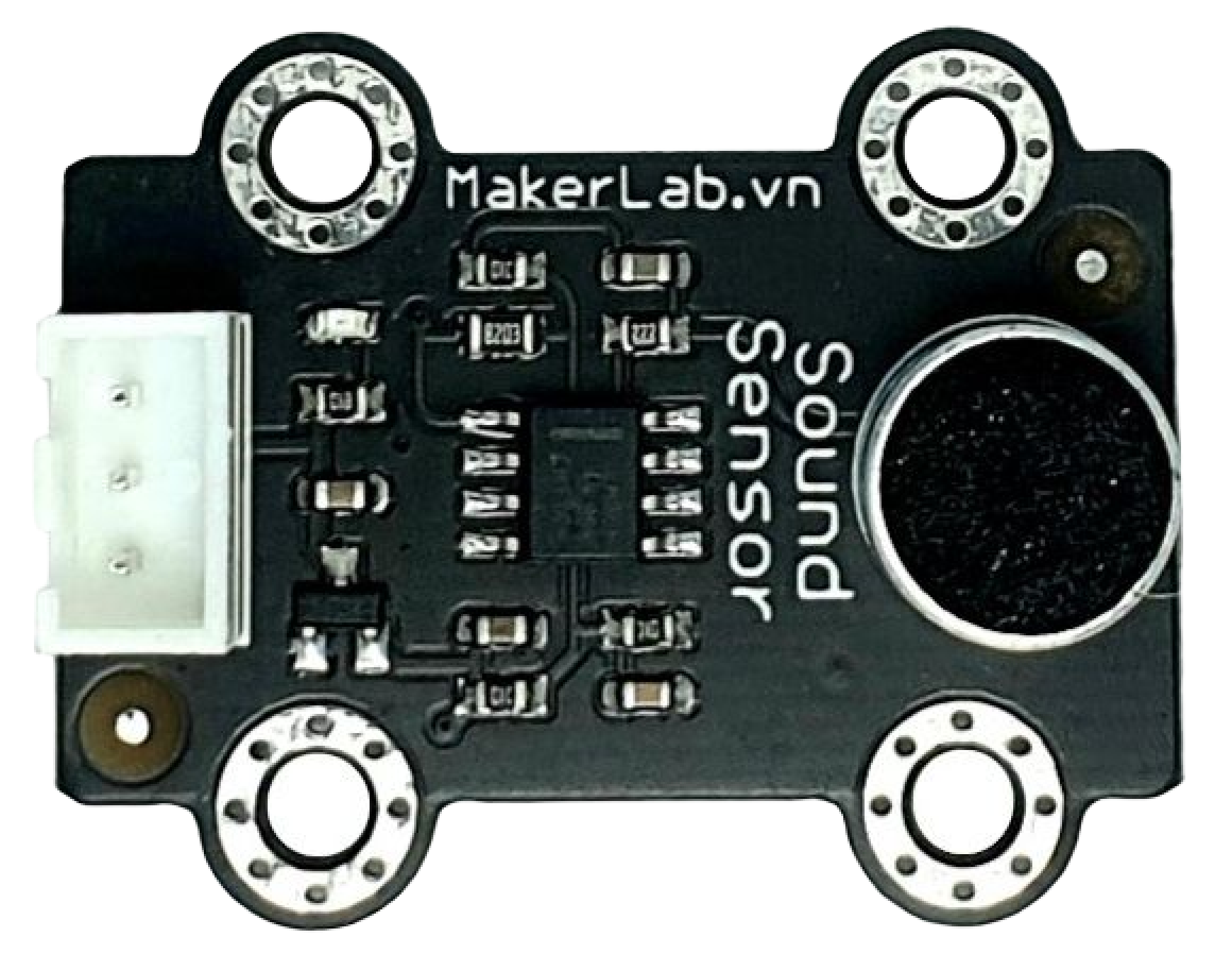
The MKE-S06 Sound Sensor is a compact and versatile electronic component designed to detect ambient sound levels and convert them into electrical signals. This sensor is commonly used in a variety of applications such as noise level monitoring, security systems, and interactive art installations. Its ease of use makes it suitable for hobbyists and professionals alike, allowing for sound-activated projects and experiments.
Explore Projects Built with MKE-S06 Sound Sensor
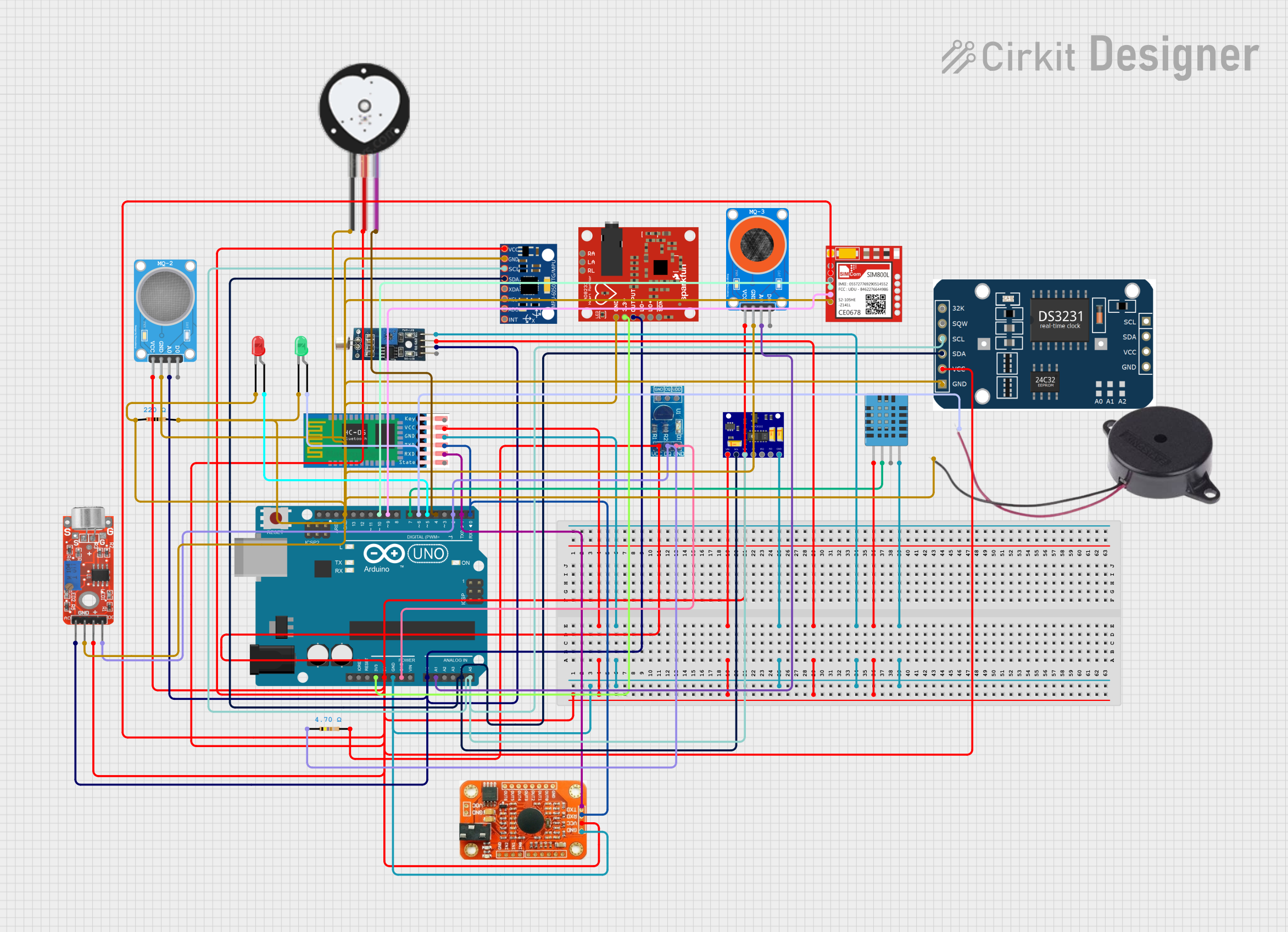

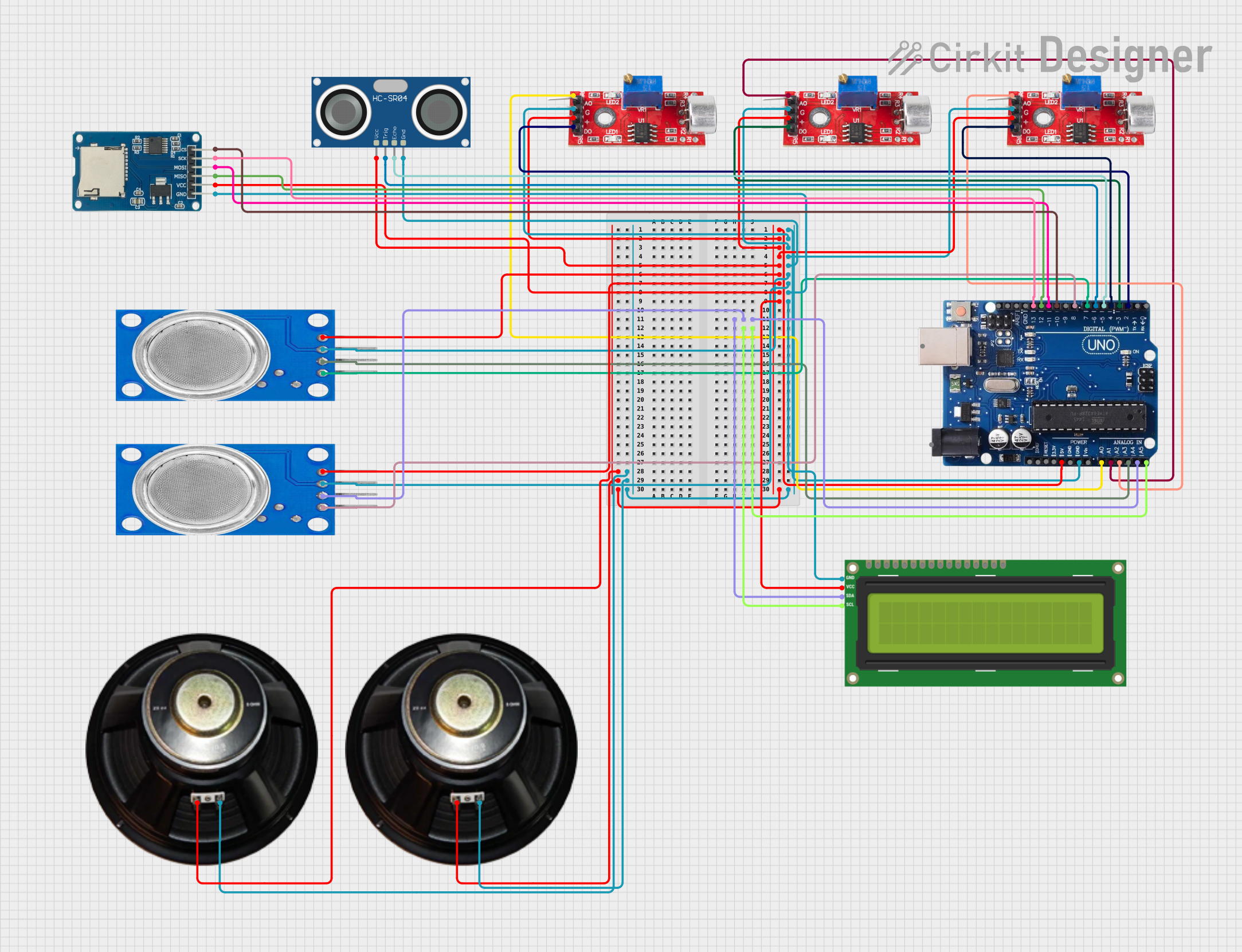
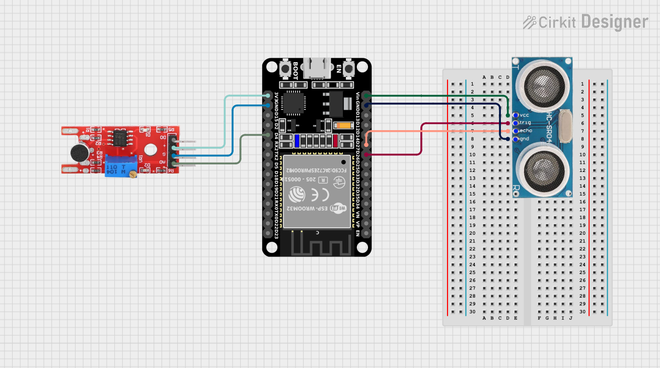
Explore Projects Built with MKE-S06 Sound Sensor
Common Applications and Use Cases
- Sound-triggered alarms
- Environmental noise measurement
- Interactive exhibits
- Voice-activated devices
- Home automation systems
Technical Specifications
Key Technical Details
- Operating Voltage: 3.3V to 5V DC
- Output Signal: Analog (0V to Vcc)
- Frequency Range: 50 Hz to 20 kHz
- Sensitivity: Adjustable via onboard potentiometer
Pin Configuration and Descriptions
| Pin Number | Pin Name | Description |
|---|---|---|
| 1 | VCC | Power supply (3.3V to 5V DC) |
| 2 | GND | Ground |
| 3 | AOUT | Analog output signal |
| 4 | DOUT | Digital output signal (threshold-based) |
Usage Instructions
How to Use the MKE-S06 Sound Sensor in a Circuit
- Powering the Sensor: Connect the VCC pin to a 3.3V or 5V power supply and the GND pin to the ground of your circuit.
- Reading the Analog Signal: Connect the AOUT pin to an analog input pin on your microcontroller to read the sound level as an analog voltage.
- Using the Digital Output: Connect the DOUT pin to a digital input pin on your microcontroller if you want to detect sound above a certain threshold, which can be set using the onboard potentiometer.
Important Considerations and Best Practices
- Ensure that the power supply voltage matches the sensor's requirements to prevent damage.
- Adjust the sensitivity carefully to avoid false triggers or missed detections.
- Keep the sensor away from vibration sources that may cause false readings.
- Use shielded cables for connections if the sensor is placed in a noisy electrical environment.
Example Code for Arduino UNO
// Define the pin connected to the analog output of the sensor
const int soundSensorPin = A0;

void setup() {
  // Initialize serial communication at 9600 baud rate
  Serial.begin(9600);
}

void loop() {
  // Read the analog value from the sound sensor
  int sensorValue = analogRead(soundSensorPin);

  // Convert the reading to a voltage level
  float voltage = sensorValue * (5.0 / 1023.0);

  // Print the voltage level to the Serial Monitor
  Serial.print("Voltage: ");
  Serial.println(voltage);

  // Wait for a short period before reading again
  delay(200);
}
Troubleshooting and FAQs
Common Issues Users Might Face
- Inconsistent Readings: If the sensor provides inconsistent readings, check for loose connections and ensure that the sensor is not subjected to mechanical vibrations.
- No Output Signal: Verify that the sensor is correctly powered and that the pins are connected to the correct microcontroller inputs.
- Too Sensitive or Insensitive: Adjust the onboard potentiometer to fine-tune the sensor's sensitivity.
Solutions and Tips for Troubleshooting
- Check Connections: Ensure all connections are secure and free from corrosion or damage.
- Power Supply: Confirm that the power supply is stable and within the specified voltage range.
- Interference: Minimize electrical noise by keeping the sensor away from high-power devices and using shielded cables.
FAQs
Q: Can the MKE-S06 Sound Sensor differentiate between different sounds or frequencies?
A: The MKE-S06 Sound Sensor does not differentiate between sounds or frequencies. It measures the overall sound level in the environment.
Q: How do I adjust the threshold for the digital output?
A: Turn the onboard potentiometer clockwise or counterclockwise to increase or decrease the threshold level for the digital output.
Q: Is it possible to use multiple MKE-S06 sensors in one project?
A: Yes, you can use multiple sensors in a project, but ensure each sensor's output is read by a separate input pin on your microcontroller.
Q: What is the maximum distance at which the sensor can detect sound?
A: The maximum detection range depends on the ambient noise level and the sensitivity setting. It is generally effective for close to medium-range applications.