How to Use maker line sensor: Examples, Pinouts, and Specs
Introduction
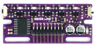
The Maker Line Sensor, manufactured by Maker Drive (Part ID: Line Sensor), is a compact and efficient device designed for detecting lines or edges on surfaces. It is widely used in robotics and automation projects, particularly for line-following robots or navigation systems. The sensor operates by emitting infrared (IR) light and detecting its reflection, allowing it to differentiate between light and dark surfaces.
Explore Projects Built with maker line sensor


Explore Projects Built with maker line sensor
Common Applications and Use Cases
- Line-following robots for educational and industrial purposes
- Automated guided vehicles (AGVs) for navigation
- Edge detection in robotic systems
- Obstacle avoidance in simple robotics
- Path tracking in maze-solving robots
Technical Specifications
The Maker Line Sensor is designed for ease of use and compatibility with microcontrollers like Arduino. Below are its key technical details:
General Specifications
| Parameter | Value |
|---|---|
| Operating Voltage | 3.3V to 5V |
| Operating Current | ~20mA |
| Detection Range | 1mm to 10mm |
| Output Type | Digital (High/Low) |
| Sensor Type | Infrared (IR) Reflective |
| Dimensions | 25mm x 10mm x 5mm |
| Manufacturer Part ID | Line Sensor |
Pin Configuration and Descriptions
The Maker Line Sensor typically has three pins for interfacing with a microcontroller. The pinout is as follows:
| Pin Name | Pin Number | Description |
|---|---|---|
| VCC | 1 | Power supply input (3.3V to 5V) |
| GND | 2 | Ground connection |
| OUT | 3 | Digital output signal (High/Low) |
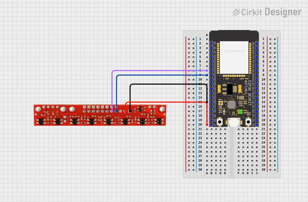
Usage Instructions
How to Use the Maker Line Sensor in a Circuit
- Power the Sensor: Connect the
VCCpin to a 3.3V or 5V power source and theGNDpin to the ground of your circuit. - Connect the Output: Attach the
OUTpin to a digital input pin on your microcontroller (e.g., Arduino). - Position the Sensor: Place the sensor approximately 2-5mm above the surface to ensure optimal detection of lines or edges.
- Calibrate the Sensor: Test the sensor on the intended surface to ensure it correctly detects light and dark areas. Adjust the height or angle if necessary.
Important Considerations and Best Practices
- Surface Contrast: The sensor works best on surfaces with high contrast (e.g., black lines on a white background).
- Ambient Light: Avoid using the sensor in environments with strong ambient IR light, as it may interfere with detection.
- Distance: Maintain the recommended distance (1mm to 10mm) between the sensor and the surface for accurate readings.
- Pull-up Resistor: If the output signal is unstable, consider using a pull-up resistor on the
OUTpin.
Example Code for Arduino UNO
Below is an example of how to use the Maker Line Sensor with an Arduino UNO to detect a line:
// Define the pin connected to the sensor's OUT pin
const int sensorPin = 2; // Digital pin 2 on Arduino UNO

void setup() {
  pinMode(sensorPin, INPUT); // Set the sensor pin as input
  Serial.begin(9600);        // Initialize serial communication
}

void loop() {
  int sensorValue = digitalRead(sensorPin); // Read the sensor output

  if (sensorValue == HIGH) {
    // Sensor detects a light surface
    Serial.println("Light surface detected");
  } else {
    // Sensor detects a dark surface (line)
    Serial.println("Dark surface (line) detected");
  }

  delay(100); // Small delay for stability
}
Troubleshooting and FAQs
Common Issues and Solutions
Sensor Not Detecting Lines
- Cause: Incorrect positioning or insufficient surface contrast.
- Solution: Adjust the sensor height or use a surface with higher contrast.
Unstable Output Signal
- Cause: Electrical noise or improper connections.
- Solution: Use a pull-up resistor on the
OUTpin and ensure secure connections.
Interference from Ambient Light
- Cause: Strong IR light sources in the environment.
- Solution: Shield the sensor from ambient light or use it in a controlled environment.
No Output Signal
- Cause: Incorrect wiring or insufficient power supply.
- Solution: Double-check the wiring and ensure the power supply meets the sensor's requirements.
FAQs
Q: Can the Maker Line Sensor detect colors?
A: No, the sensor is designed to detect light and dark surfaces based on IR reflection, not specific colors.
Q: What is the maximum detection range of the sensor?
A: The sensor can detect surfaces within a range of 1mm to 10mm.
Q: Is the sensor compatible with 3.3V microcontrollers?
A: Yes, the sensor operates with both 3.3V and 5V power supplies, making it compatible with a wide range of microcontrollers.
Q: Can I use multiple sensors for a line-following robot?
A: Yes, you can use multiple sensors to improve accuracy and enable more complex navigation algorithms.
By following this documentation, you can effectively integrate the Maker Line Sensor into your projects and troubleshoot any issues that arise.