Cirkit Designer Logo
Cirkit Designer
Your all-in-one circuit design IDE
Home / 
Component Documentation

How to Use Adafruit WINC1500 uFL Antenna Breakout: Examples, Pinouts, and Specs

Image of Adafruit WINC1500 uFL Antenna Breakout
Cirkit Designer LogoDesign with Adafruit WINC1500 uFL Antenna Breakout in Cirkit Designer

Introduction

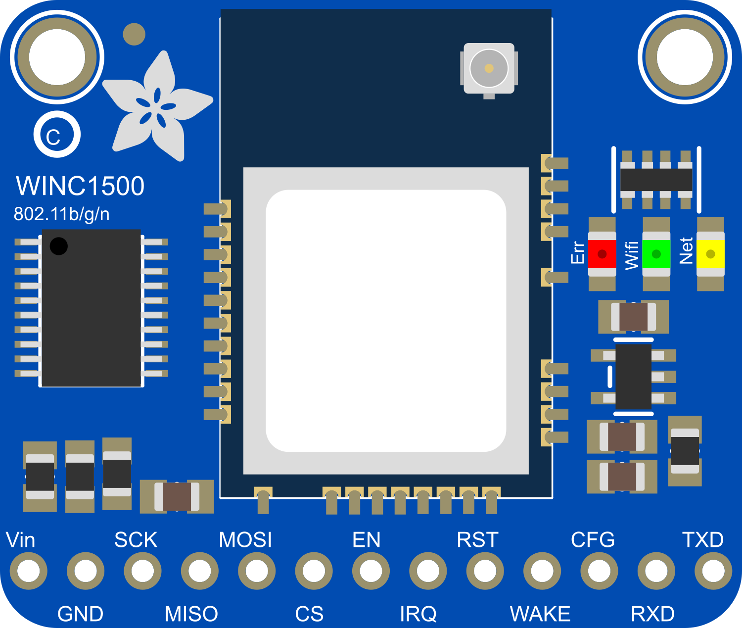
The Adafruit WINC1500 uFL Antenna Breakout is a specialized wireless module that enables microcontrollers to connect to a WiFi network. It features the WINC1500, a powerful WiFi network controller capable of both TCP and UDP protocols. This breakout is particularly useful for Internet of Things (IoT) projects, remote sensor monitoring, and any application requiring wireless data transmission.

Explore Projects Built with Adafruit WINC1500 uFL Antenna Breakout

Use Cirkit Designer to design, explore, and prototype these projects online. Some projects support real-time simulation. Click "Open Project" to start designing instantly!
Arduino UNO WiFi with Heart Pulse and Temperature Monitoring
Image of BioTrackers: A project utilizing Adafruit WINC1500 uFL Antenna Breakout in a practical application
This circuit features an Arduino UNO R4 WiFi microcontroller connected to a Heart Pulse Sensor and an SHT1x-Breakout sensor. The Arduino is configured to read heart pulse signals from the Heart Pulse Sensor on analog pin A0 and temperature/humidity data from the SHT1x-Breakout sensor via the I2C interface on pins A4 (DATA) and A5 (SCK). Both sensors are powered by the Arduino's 5V output, and their ground pins are connected to the Arduino's ground.
Cirkit Designer LogoOpen Project in Cirkit Designer
Arduino UNO WiFi Sensor Data Acquisition and Display System
Image of Senior Design: A project utilizing Adafruit WINC1500 uFL Antenna Breakout in a practical application
This circuit features an Arduino UNO R4 WiFi microcontroller interfacing with a 4-channel ADC to read from various sensors and display data on an I2C LCD screen. A pushbutton provides user input, and a DC-DC buck converter regulates the power supply from a 12V source.
Cirkit Designer LogoOpen Project in Cirkit Designer
Arduino Pro Mini FM Radio with LCD Display and Battery Power
Image of DIY FM Radio RDA5807M V2: A project utilizing Adafruit WINC1500 uFL Antenna Breakout in a practical application
This circuit is a portable FM radio receiver with an integrated display and audio output. It uses an Arduino Pro Mini to control an RDA5807M FM receiver module, an ADS1115 ADC for additional analog inputs, and a PAM8403 amplifier to drive loudspeakers. The circuit also includes a rotary encoder for user input, an LCD screen for displaying information, and a boost converter for power management.
Cirkit Designer LogoOpen Project in Cirkit Designer
Arduino UNO and RFM95 LoRa Transceiver with Inductor for Wireless Communication
Image of transmitter: A project utilizing Adafruit WINC1500 uFL Antenna Breakout in a practical application
This circuit integrates an Arduino UNO with an RFM95 LoRa module for wireless communication. The Arduino provides power and control signals to the RFM95, while an inductor is connected to the antenna pin of the RFM95 to facilitate signal transmission. The setup is designed for applications requiring long-range, low-power wireless data transmission.
Cirkit Designer LogoOpen Project in Cirkit Designer

Explore Projects Built with Adafruit WINC1500 uFL Antenna Breakout

Use Cirkit Designer to design, explore, and prototype these projects online. Some projects support real-time simulation. Click "Open Project" to start designing instantly!
Image of BioTrackers: A project utilizing Adafruit WINC1500 uFL Antenna Breakout in a practical application
Arduino UNO WiFi with Heart Pulse and Temperature Monitoring
This circuit features an Arduino UNO R4 WiFi microcontroller connected to a Heart Pulse Sensor and an SHT1x-Breakout sensor. The Arduino is configured to read heart pulse signals from the Heart Pulse Sensor on analog pin A0 and temperature/humidity data from the SHT1x-Breakout sensor via the I2C interface on pins A4 (DATA) and A5 (SCK). Both sensors are powered by the Arduino's 5V output, and their ground pins are connected to the Arduino's ground.
Cirkit Designer LogoOpen Project in Cirkit Designer
Image of Senior Design: A project utilizing Adafruit WINC1500 uFL Antenna Breakout in a practical application
Arduino UNO WiFi Sensor Data Acquisition and Display System
This circuit features an Arduino UNO R4 WiFi microcontroller interfacing with a 4-channel ADC to read from various sensors and display data on an I2C LCD screen. A pushbutton provides user input, and a DC-DC buck converter regulates the power supply from a 12V source.
Cirkit Designer LogoOpen Project in Cirkit Designer
Image of DIY FM Radio RDA5807M V2: A project utilizing Adafruit WINC1500 uFL Antenna Breakout in a practical application
Arduino Pro Mini FM Radio with LCD Display and Battery Power
This circuit is a portable FM radio receiver with an integrated display and audio output. It uses an Arduino Pro Mini to control an RDA5807M FM receiver module, an ADS1115 ADC for additional analog inputs, and a PAM8403 amplifier to drive loudspeakers. The circuit also includes a rotary encoder for user input, an LCD screen for displaying information, and a boost converter for power management.
Cirkit Designer LogoOpen Project in Cirkit Designer
Image of transmitter: A project utilizing Adafruit WINC1500 uFL Antenna Breakout in a practical application
Arduino UNO and RFM95 LoRa Transceiver with Inductor for Wireless Communication
This circuit integrates an Arduino UNO with an RFM95 LoRa module for wireless communication. The Arduino provides power and control signals to the RFM95, while an inductor is connected to the antenna pin of the RFM95 to facilitate signal transmission. The setup is designed for applications requiring long-range, low-power wireless data transmission.
Cirkit Designer LogoOpen Project in Cirkit Designer

Common Applications and Use Cases

  • IoT devices
  • Remote data logging
  • Wireless sensor networks
  • Home automation systems
  • WiFi-enabled robotics

Technical Specifications

Key Technical Details

  • WiFi Chipset: ATWINC1500-MR210PB
  • Frequency Band: 2.4 GHz ISM Band
  • Wireless Standards: IEEE 802.11 b/g/n
  • Data Rates: Up to 72 Mbps at 20 MHz bandwidth
  • Security Protocols: WEP, WPA/WPA2 PSK, and Enterprise
  • Interface: SPI
  • Voltage Supply: 3.3V (Do not exceed 3.3V)
  • Current Consumption: Max 170 mA during TX, 100 mA during RX
  • Operating Temperature: -40°C to +85°C

Pin Configuration and Descriptions

Pin Number Name Description
1 GND Ground connection
2 3V3 3.3V power supply input
3 EN Chip enable pin (active high)
4 RST Reset pin (active low)
5 SCK SPI clock
6 MISO Master In Slave Out for SPI
7 MOSI Master Out Slave In for SPI
8 CS SPI chip select (active low)
9 IRQ Interrupt request (active low)
10 uFL uFL antenna connector

Usage Instructions

How to Use the Component in a Circuit

  1. Power Supply: Connect the 3V3 pin to a 3.3V power source and the GND pin to the ground.
  2. SPI Communication: Connect the SCK, MISO, MOSI, and CS pins to the corresponding SPI pins on your microcontroller.
  3. Enable and Reset: Connect the EN pin to a digital output for enabling the module and the RST pin to another digital output for resetting the module.
  4. Antenna: Attach a uFL-compatible antenna to the uFL connector for wireless communication.

Important Considerations and Best Practices

  • Ensure that the power supply is stable and does not exceed 3.3V.
  • Use a level shifter if you are interfacing with a 5V microcontroller.
  • Keep the antenna area clear from metal objects to avoid interference.
  • Follow proper ESD precautions when handling the breakout to prevent damage.

Example Code for Arduino UNO

#include <SPI.h>
#include <WiFi101.h>

// Your WiFi network credentials
char ssid[] = "your_network_SSID";
char pass[] = "your_password";

void setup() {
  // Initialize serial communication
  Serial.begin(9600);

  // Check for the presence of the shield
  if (WiFi.status() == WL_NO_SHIELD) {
    Serial.println("WiFi shield not present");
    // Don't continue if the shield is not present
    while (true);
  }

  // Attempt to connect to WiFi network
  while (WiFi.begin(ssid, pass) != WL_CONNECTED) {
    Serial.print("Attempting to connect to SSID: ");
    Serial.println(ssid);
    // Wait 10 seconds before retrying
    delay(10000);
  }

  Serial.println("Connected to wifi");
  printWiFiStatus();
}

void loop() {
  // Nothing here for now.
}

void printWiFiStatus() {
  // Print the SSID of the network you're attached to
  Serial.print("SSID: ");
  Serial.println(WiFi.SSID());

  // Print your board's IP address
  IPAddress ip = WiFi.localIP();
  Serial.print("IP Address: ");
  Serial.println(ip);

  // Print the received signal strength
  long rssi = WiFi.RSSI();
  Serial.print("Signal strength (RSSI):");
  Serial.print(rssi);
  Serial.println(" dBm");
}

Troubleshooting and FAQs

Common Issues Users Might Face

  • WiFi Connection Failure: Ensure the SSID and password are correct. Check the signal strength and distance from the router.
  • Module Not Responding: Verify the wiring, especially the SPI connections and power supply. Ensure the EN and RST pins are correctly managed in your code.
  • Intermittent Connectivity: Check for sources of wireless interference and ensure the antenna is properly connected.

Solutions and Tips for Troubleshooting

  • Power Issues: Use a dedicated 3.3V regulator if your microcontroller cannot provide a stable voltage.
  • SPI Communication: Double-check the SPI pin connections and ensure they match the code configuration.
  • Antenna Placement: Position the antenna away from metal objects and electronic devices that may cause interference.

FAQs

Q: Can I use the Adafruit WINC1500 with a 5V microcontroller? A: Yes, but you will need a level shifter to convert the 5V signals to 3.3V to avoid damaging the module.

Q: How can I extend the range of the WiFi signal? A: Use a higher gain antenna, and ensure it is placed in an optimal position, away from obstructions and interference sources.

Q: What should I do if I'm getting poor signal strength? A: Check the antenna connection and consider moving the device closer to the WiFi router or using a WiFi range extender.

Q: Is it possible to use multiple WINC1500 modules with one microcontroller? A: Yes, it is possible by using separate CS (chip select) lines for each module and managing them appropriately in your code.

Remember to always refer to the official datasheet and the Adafruit WINC1500 uFL Antenna Breakout guide for the most accurate and detailed information.