How to Use Nano 3.0 ATmega328P Type-C USB CH340 Controller Board: Examples, Pinouts, and Specs
Introduction
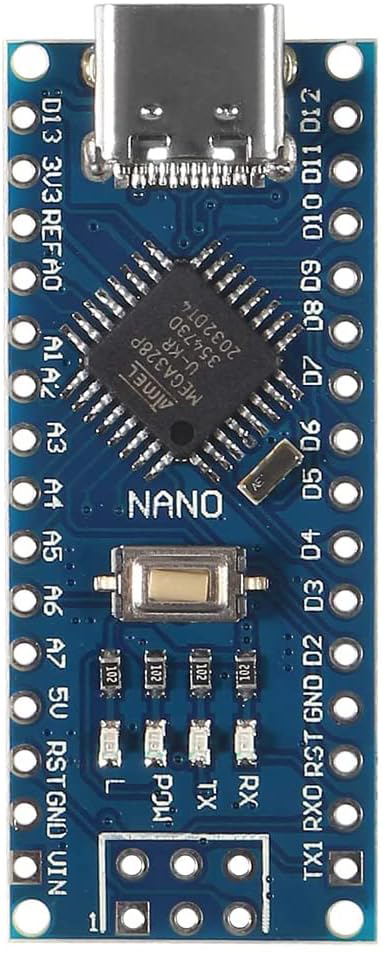
The Nano 3.0 ATmega328P Type-C USB CH340 Controller Board by HiLetgo is a compact and versatile microcontroller development platform. It is based on the popular ATmega328P microcontroller and features a Type-C USB port for programming and power, with the CH340 chip serving as the USB-to-serial converter. This board is widely used in electronics projects, from simple DIY tasks to complex prototypes, due to its small form factor and ease of use.
Common applications include:
- Hobbyist electronics projects
- Prototyping for embedded systems
- Educational purposes in schools and workshops
- IoT devices and smart home applications
- Robotics and control systems
Explore Projects Built with Nano 3.0 ATmega328P Type-C USB CH340 Controller Board


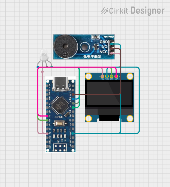
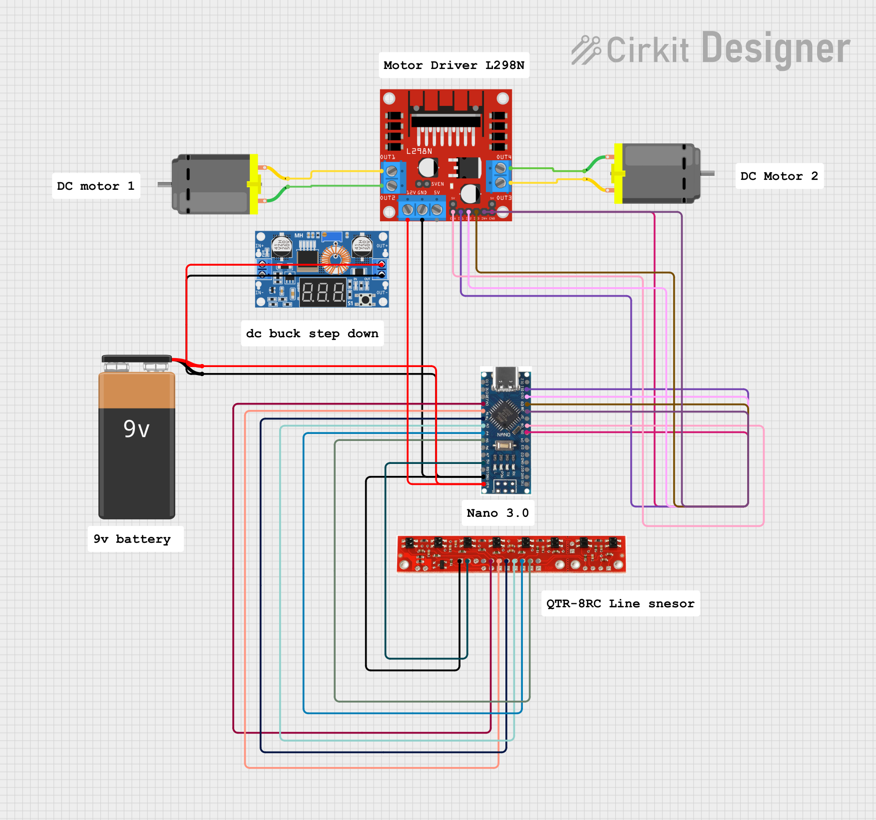
Explore Projects Built with Nano 3.0 ATmega328P Type-C USB CH340 Controller Board
Technical Specifications
Key Technical Details
- Microcontroller: ATmega328P
- Operating Voltage: 5V
- Input Voltage (recommended): 7-12V
- Input Voltage (limits): 6-20V
- Digital I/O Pins: 14 (of which 6 provide PWM output)
- Analog Input Pins: 8
- DC Current per I/O Pin: 40 mA
- DC Current for 3.3V Pin: 50 mA
- Flash Memory: 32 KB (ATmega328P) of which 2 KB used by bootloader
- SRAM: 2 KB (ATmega328P)
- EEPROM: 1 KB (ATmega328P)
- Clock Speed: 16 MHz
- USB Chip: CH340
- USB Connector: Type-C
Pin Configuration and Descriptions
| Pin Number | Function | Description |
|---|---|---|
| 1 | RESET | Used to reset the microcontroller |
| 2-13 | Digital I/O | Digital input/output pins, PWM on pins 3, 5, 6, 9, 10, and 11 |
| 14-21 | Analog Input | Analog input pins A0-A7 |
| 22 | 5V | Output from the onboard 5V regulator |
| 23 | 3V3 | Output from the onboard 3.3V regulator |
| 24 | GND | Ground |
| 25 | REF | Reference voltage for the analog inputs |
| 26 | RESET | Another pin for resetting the microcontroller |
| 27-30 | GND, RST, VCC, 2X3 PINS | ISP header for direct programming of the microcontroller |
Usage Instructions
How to Use the Component in a Circuit
Powering the Board:
- Connect the board to a computer via a Type-C USB cable to power it and program it.
- Alternatively, apply an external power supply (7-12V recommended) to the VIN pin.
Programming the Board:
- Select "Arduino Nano" as the board type in the Arduino IDE.
- Choose "ATmega328P" as the processor.
- Select the appropriate COM port for the CH340 USB-to-serial chip.
Connecting Peripherals:
- Use the digital and analog pins to connect sensors, actuators, and other peripherals.
- Ensure that the connected devices are compatible with the voltage and current specifications of the board's pins.
Important Considerations and Best Practices
- Always disconnect the board from power sources before making or altering connections.
- Do not exceed the voltage and current limits to prevent damage to the board.
- Use a current limiting resistor when connecting LEDs to the digital I/O pins.
- Utilize the onboard 3.3V regulator when interfacing with 3.3V logic level components.
Troubleshooting and FAQs
Common Issues
Board not recognized by the computer:
- Ensure the Type-C USB cable is properly connected and functioning.
- Install the CH340 drivers if they are not already installed on your computer.
Incorrect voltage output:
- Check the power supply and connections.
- Verify that the board is not in a brown-out state due to an insufficient power supply.
Program not running as expected:
- Double-check the code for errors.
- Ensure that the correct board and processor are selected in the Arduino IDE.
Solutions and Tips for Troubleshooting
- If the board is not recognized, try a different USB port or cable.
- For driver issues, download the latest CH340 drivers from the manufacturer's website.
- Use a multimeter to check voltages and continuity in your circuit.
- Simplify your setup to isolate the problem.
FAQs
Q: Can I power the Nano 3.0 board with more than 12V? A: While the board can technically handle up to 20V, it is recommended to stay within the 7-12V range to prevent overheating and potential damage.
Q: How do I reset the board? A: You can reset the board by briefly connecting the RESET pin to GND or by pressing the onboard reset button.
Q: What should I do if I'm getting upload errors? A: Check your connections, ensure the correct board and processor are selected, and that the correct COM port is chosen. Also, verify that the bootloader on the board is functioning correctly.
Example Code for Arduino UNO
// Blink an LED connected to pin 13

void setup() {
  pinMode(13, OUTPUT); // Set pin 13 as an output
}

void loop() {
  digitalWrite(13, HIGH);   // Turn the LED on
  delay(1000);              // Wait for a second
  digitalWrite(13, LOW);    // Turn the LED off
  delay(1000);              // Wait for a second
}
Note: The above code is for demonstration purposes and assumes an LED is connected to pin 13 with a suitable current-limiting resistor.