
How to Use AUDIO-JACK2: Examples, Pinouts, and Specs
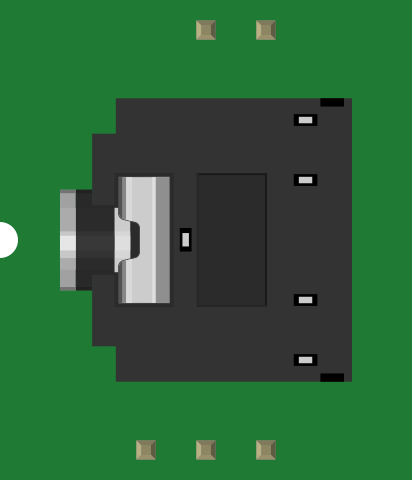
 Design with AUDIO-JACK2 in Cirkit Designer
Introduction
The AUDIO-JACK2 by SparkFun is a versatile audio connector designed for interfacing audio devices. It is commonly used to connect headphones, microphones, or other audio equipment via a 3.5mm or 1/4 inch plug. This component is ideal for audio signal transmission in consumer electronics, DIY audio projects, and professional audio equipment.
Explore Projects Built with AUDIO-JACK2
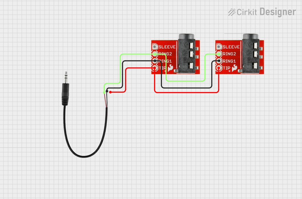 Open Project in Cirkit Designer
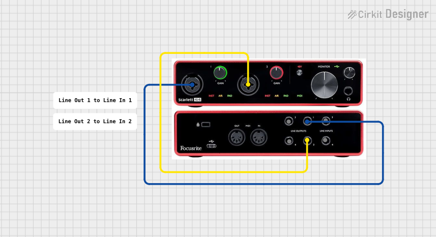 Open Project in Cirkit Designer
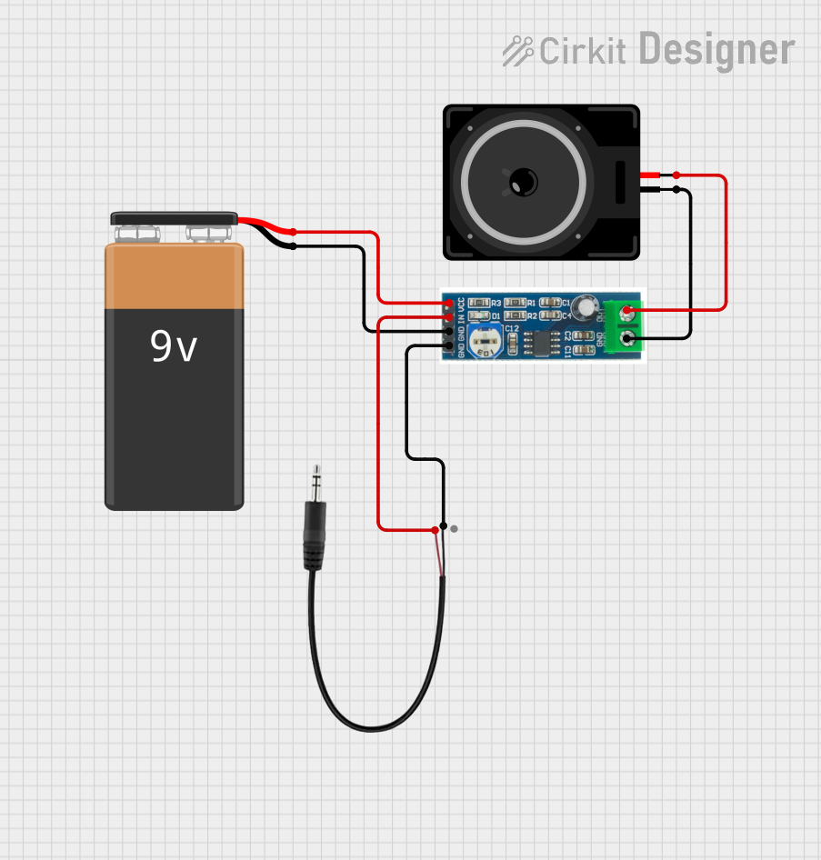 Open Project in Cirkit Designer
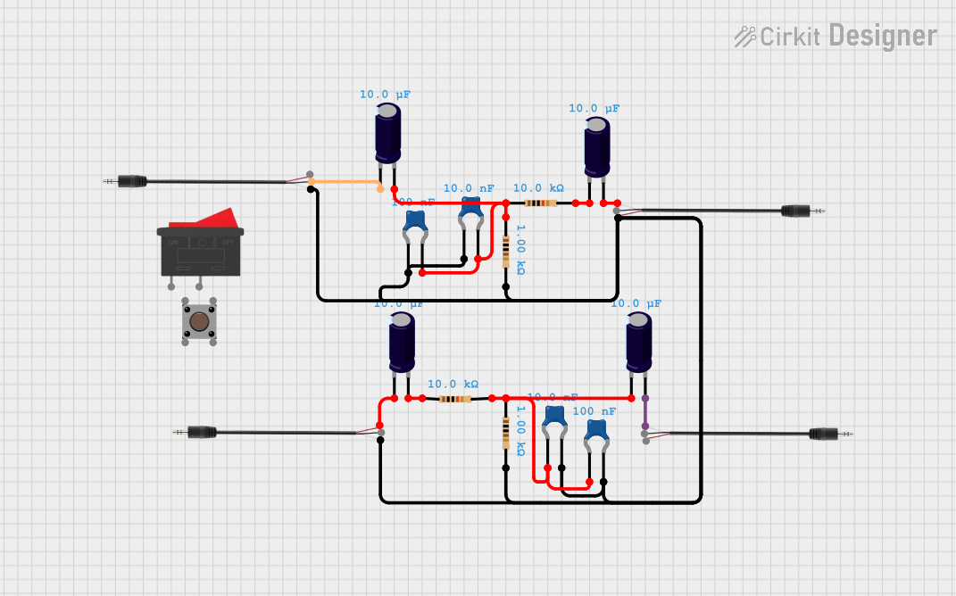 Open Project in Cirkit Designer
Explore Projects Built with AUDIO-JACK2
Open Project in Cirkit DesignerOpen Project in Cirkit DesignerOpen Project in Cirkit DesignerOpen Project in Cirkit DesignerCommon Applications and Use Cases
- Connecting headphones or earphones to audio devices
- Interfacing microphones with recording equipment
- Audio signal routing in DIY electronics projects
- Integration into audio amplifiers, mixers, and soundboards
- Repair or replacement of damaged audio jacks in consumer devices
Technical Specifications
The following table outlines the key technical details of the AUDIO-JACK2:
| Parameter | Specification |
|---|---|
| Manufacturer | SparkFun |
| Part ID | AUDIO-JACK2 |
| Connector Type | 3.5mm or 1/4 inch audio jack |
| Number of Contacts | 3 (Stereo: Left, Right, Ground) |
| Mounting Style | Through-hole or panel mount |
| Material | Metal contacts with plastic housing |
| Maximum Voltage Rating | 12V |
| Maximum Current Rating | 1A |
| Operating Temperature | -20°C to 70°C |
Pin Configuration and Descriptions
The AUDIO-JACK2 typically features three pins for stereo audio connections. The pinout is as follows:
| Pin | Name | Description |
|---|---|---|
| 1 | Tip (T) | Left audio channel signal |
| 2 | Ring (R) | Right audio channel signal |
| 3 | Sleeve (S) | Ground connection (common for both channels) |
Note: For mono audio connections, only the Tip and Sleeve are used.
Usage Instructions
How to Use the AUDIO-JACK2 in a Circuit
Mounting the Connector:
- For through-hole mounting, solder the pins of the AUDIO-JACK2 to the PCB.
- For panel mounting, secure the connector to the panel using the provided nut or clip.
Wiring the Pins:
- Connect the Tip (T) pin to the left audio channel signal.
- Connect the Ring (R) pin to the right audio channel signal.
- Connect the Sleeve (S) pin to the ground of the circuit.
Testing the Connection:
- Use a multimeter to verify continuity between the pins and the corresponding contacts on the plug.
- Ensure there are no short circuits between the pins.
Important Considerations and Best Practices
- Signal Integrity: Use shielded cables to minimize noise and interference in audio signals.
- Current and Voltage Limits: Do not exceed the maximum voltage (12V) or current (1A) ratings to avoid damage.
- Proper Grounding: Ensure the ground (Sleeve) is properly connected to prevent hum or noise in the audio signal.
- Plug Compatibility: Verify that the plug (3.5mm or 1/4 inch) matches the connector type.
Example: Connecting AUDIO-JACK2 to an Arduino UNO
The AUDIO-JACK2 can be used to interface audio signals with an Arduino UNO for audio processing or signal detection. Below is an example of how to connect the AUDIO-JACK2 to an analog input pin on the Arduino:
Circuit Diagram
- Tip (T): Connect to Arduino analog pin (e.g., A0).
- Sleeve (S): Connect to Arduino GND.
- Ring (R): Leave unconnected if only one channel is used.
Arduino Code Example
// Example code to read audio signal from AUDIO-JACK2 using Arduino UNO
const int audioPin = A0; // Analog pin connected to Tip (T) of AUDIO-JACK2

void setup() {
  Serial.begin(9600); // Initialize serial communication
}

void loop() {
  int audioSignal = analogRead(audioPin); // Read audio signal from the jack
  Serial.println(audioSignal); // Print the signal value to the Serial Monitor
  delay(10); // Small delay for stability
}
Note: This example reads the audio signal as an analog voltage. For audio processing, additional circuitry (e.g., an amplifier or filter) may be required.
Troubleshooting and FAQs
Common Issues and Solutions
No Audio Signal Detected:
- Verify that the plug is fully inserted into the AUDIO-JACK2 connector.
- Check the solder joints for proper connections.
- Ensure the audio source is functioning correctly.
Noise or Hum in the Audio Signal:
- Use shielded cables to reduce electromagnetic interference.
- Ensure the ground (Sleeve) is properly connected to the circuit ground.
Short Circuit Between Pins:
- Inspect the soldering for accidental bridges between pins.
- Use a multimeter to check for continuity and isolate the issue.
Connector Feels Loose:
- Ensure the panel mount is securely fastened.
- Replace the connector if the internal contacts are worn out.
FAQs
Q: Can the AUDIO-JACK2 handle mono audio signals?
A: Yes, the AUDIO-JACK2 can handle mono signals by using only the Tip (T) and Sleeve (S) pins.
Q: Is the AUDIO-JACK2 compatible with both 3.5mm and 1/4 inch plugs?
A: The AUDIO-JACK2 is available in variants for either 3.5mm or 1/4 inch plugs. Ensure you select the correct version for your application.
Q: Can I use the AUDIO-JACK2 for digital audio signals?
A: The AUDIO-JACK2 is primarily designed for analog audio signals. For digital audio, ensure the signal levels and impedance are compatible.
Q: What is the maximum cable length I can use with the AUDIO-JACK2?
A: The maximum cable length depends on the application and signal quality requirements. For best results, use shielded cables and keep the length under 10 meters for analog audio signals.
By following this documentation, you can effectively integrate the SparkFun AUDIO-JACK2 into your audio projects and ensure reliable performance.