How to Use MAINS CAR BATTERY CHARGER: Examples, Pinouts, and Specs
Introduction
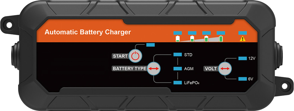
The Mains Car Battery Charger is a device designed to convert AC mains electricity into a suitable DC voltage for charging car batteries. It ensures that car batteries are maintained at optimal charge levels, extending their lifespan and ensuring they are ready for use when needed. This charger is commonly used in automotive workshops, garages, and for personal vehicle maintenance.
Explore Projects Built with MAINS CAR BATTERY CHARGER
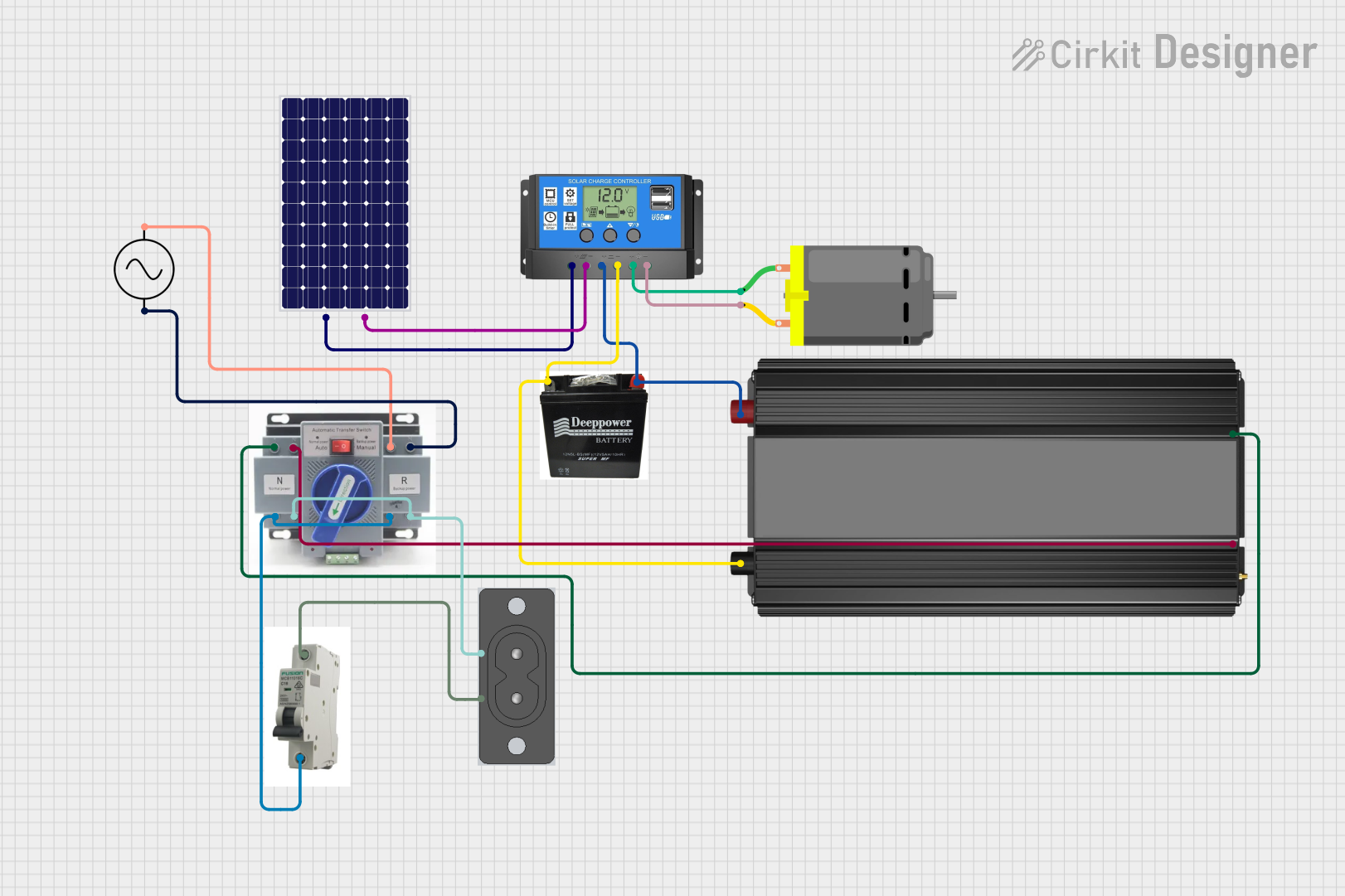

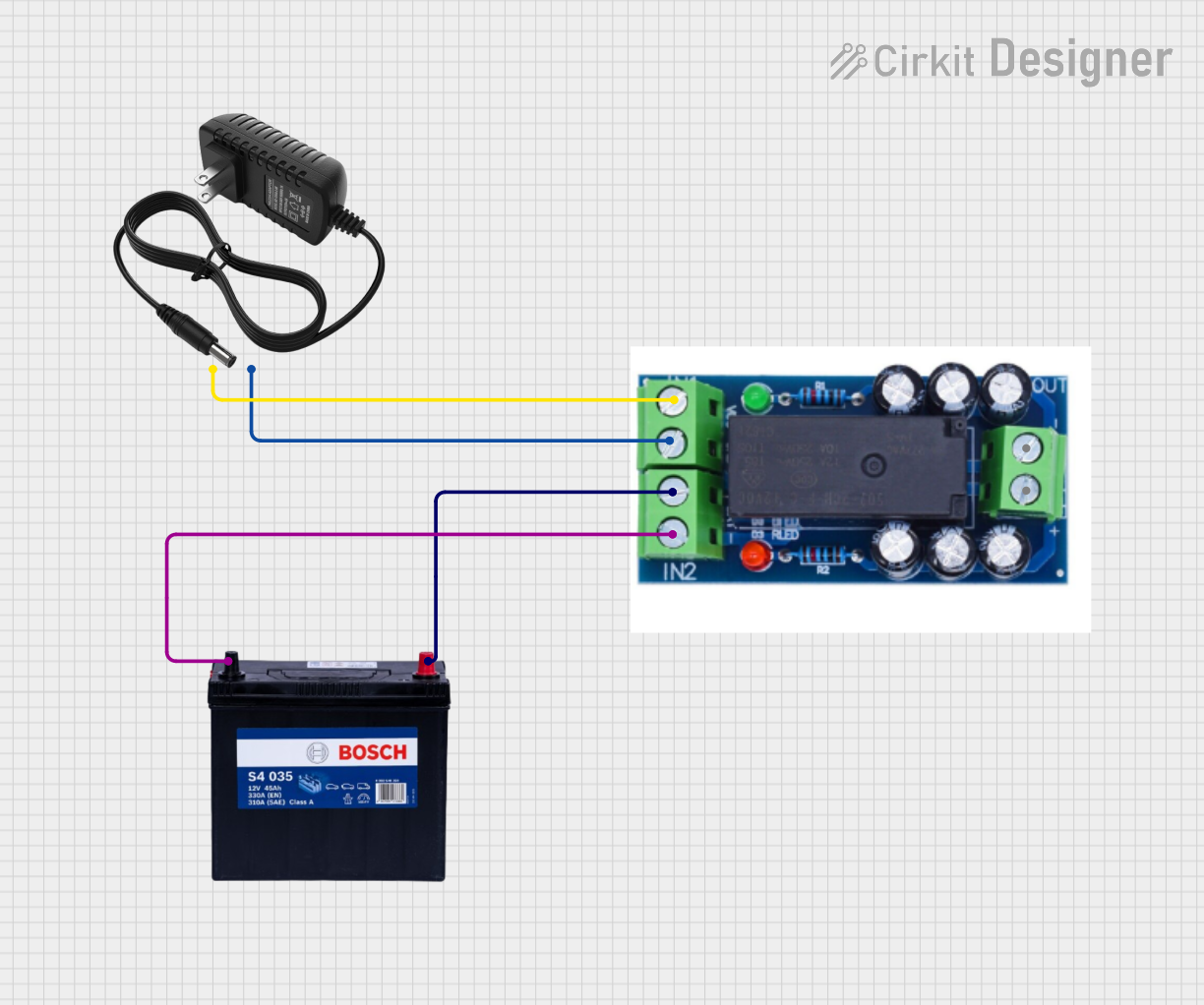
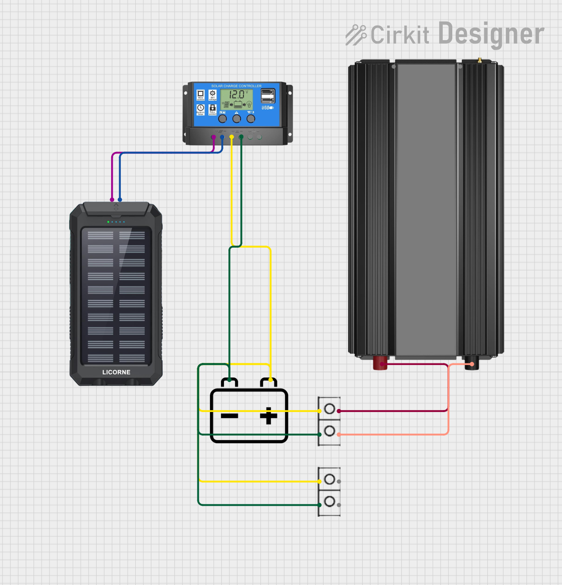
Explore Projects Built with MAINS CAR BATTERY CHARGER
Common Applications and Use Cases
- Charging 12V or 24V lead-acid car batteries.
- Maintaining battery charge during long periods of vehicle inactivity.
- Restoring discharged batteries to full capacity.
- Use in automotive repair shops and personal garages.
Technical Specifications
Key Technical Details
- Input Voltage: 100-240V AC, 50/60Hz
- Output Voltage: 12V DC or 24V DC (selectable, depending on the model)
- Output Current: 2A to 10A (varies by model)
- Battery Compatibility: Lead-acid, AGM, and Gel batteries
- Charging Modes: Constant current, constant voltage, and trickle charge
- Safety Features: Overvoltage protection, short-circuit protection, reverse polarity protection, and thermal shutdown
- Efficiency: ≥85%
- Operating Temperature: -10°C to 40°C
- Dimensions: Varies by model (e.g., 200mm x 100mm x 50mm)
- Weight: Approximately 1.5kg
Pin Configuration and Descriptions
The Mains Car Battery Charger typically has the following connections:
| Pin/Connector | Description |
|---|---|
| AC Input Plug | Connects to the mains power supply (100-240V AC). |
| Positive Output (+) | Red alligator clip or terminal for connecting to the positive terminal of the battery. |
| Negative Output (-) | Black alligator clip or terminal for connecting to the negative terminal of the battery. |
| Mode Selector | Switch or button to select charging mode (e.g., 12V/24V, trickle charge). |
| Status Indicators | LEDs or LCD display to show charging status, errors, or battery level. |
Usage Instructions
How to Use the Component in a Circuit
Prepare the Charger:
- Ensure the charger is compatible with the battery type (e.g., 12V lead-acid).
- Verify that the mains voltage matches the charger's input voltage range (100-240V AC).
Connect the Charger:
- Attach the red alligator clip to the positive terminal of the car battery.
- Attach the black alligator clip to the negative terminal of the car battery.
- Ensure the connections are secure and free of corrosion.
Select the Charging Mode:
- Use the mode selector to choose the appropriate voltage (12V or 24V) and charging mode (e.g., trickle charge for maintenance).
Power On the Charger:
- Plug the charger into a mains power outlet and switch it on.
- Observe the status indicators to confirm the charger is operating correctly.
Monitor the Charging Process:
- Check the status indicators or LCD display for charging progress.
- Once the battery is fully charged, the charger will typically switch to trickle charge or shut off automatically.
Disconnect the Charger:
- Turn off the charger and unplug it from the mains power outlet.
- Remove the alligator clips, starting with the negative terminal, followed by the positive terminal.
Important Considerations and Best Practices
- Always ensure the charger is compatible with the battery type and voltage.
- Avoid overcharging the battery, as it can lead to overheating or damage.
- Use the charger in a well-ventilated area to prevent heat buildup.
- Do not use the charger if the cables or connectors are damaged.
- Follow the manufacturer's safety guidelines and instructions.
Arduino UNO Integration
While the Mains Car Battery Charger is not directly connected to an Arduino UNO, you can use an Arduino to monitor the battery's voltage during charging. Below is an example code snippet for reading battery voltage using an Arduino UNO and a voltage divider circuit:
// Define the analog pin connected to the voltage divider
const int voltagePin = A0;

// Define the voltage divider ratio (e.g., 10:1 for a 12V battery)
const float voltageDividerRatio = 10.0;

// Define the reference voltage of the Arduino (typically 5V)
const float referenceVoltage = 5.0;

void setup() {
  Serial.begin(9600); // Initialize serial communication at 9600 baud
}

void loop() {
  int analogValue = analogRead(voltagePin); // Read the analog input
  float batteryVoltage = (analogValue * referenceVoltage / 1023.0) * voltageDividerRatio;

  // Print the battery voltage to the Serial Monitor
  Serial.print("Battery Voltage: ");
  Serial.print(batteryVoltage);
  Serial.println(" V");

  delay(1000); // Wait for 1 second before the next reading
}
Note: Ensure the voltage divider is designed to scale the battery voltage to a safe level for the Arduino's analog input (0-5V).
Troubleshooting and FAQs
Common Issues and Solutions
| Issue | Possible Cause | Solution |
|---|---|---|
| Charger does not power on | No mains power or faulty power cable | Check the mains outlet and power cable. Replace if necessary. |
| Battery is not charging | Loose or incorrect connections, or incompatible battery type | Verify connections and ensure the battery is compatible with the charger. |
| Overheating during charging | Poor ventilation or high ambient temperature | Use the charger in a well-ventilated area and avoid high-temperature environments. |
| Reverse polarity error | Alligator clips connected to the wrong battery terminals | Disconnect and reconnect the clips correctly (red to positive, black to negative). |
| Charger shuts off prematurely | Battery is fully charged or thermal protection is activated | Check the battery status and allow the charger to cool before restarting. |
FAQs
Can I use this charger for lithium-ion batteries?
- No, this charger is designed for lead-acid, AGM, and Gel batteries. Using it with lithium-ion batteries may cause damage.
How long does it take to charge a car battery?
- Charging time depends on the battery capacity and the charger's output current. For example, a 50Ah battery charged at 5A will take approximately 10 hours.
Is it safe to leave the charger connected overnight?
- Most modern chargers have automatic shutoff or trickle charge modes, making it safe to leave them connected. However, always check the manufacturer's instructions.
What should I do if the charger emits a burning smell?
- Immediately disconnect the charger from the mains and the battery. Inspect for damage and consult the manufacturer or a qualified technician.