
How to Use 350W 6-60V 3 Phase Motor Controller: Examples, Pinouts, and Specs
 Design with 350W 6-60V 3 Phase Motor Controller in Cirkit Designer
Introduction
The 350W 6-60V 3 Phase Motor Controller by RioRand is a versatile and efficient motor controller designed to regulate the speed and torque of 3-phase brushless DC (BLDC) motors. With a power handling capacity of up to 350 watts and an operating voltage range of 6 to 60 volts, this controller is ideal for a wide range of applications, including electric vehicles, robotics, industrial automation, and DIY projects.
Explore Projects Built with 350W 6-60V 3 Phase Motor Controller
 Open Project in Cirkit Designer
 Open Project in Cirkit Designer
 Open Project in Cirkit Designer
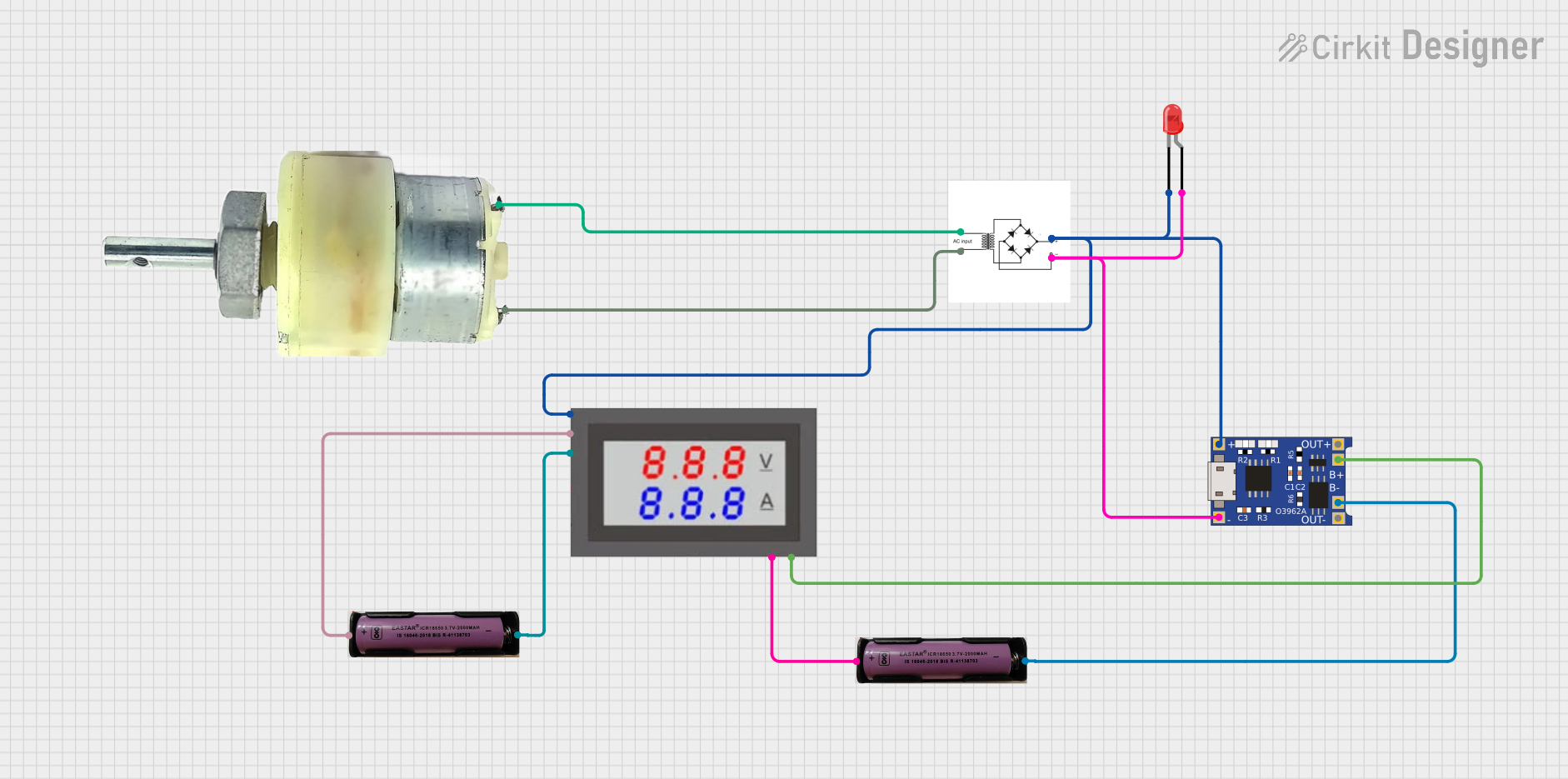 Open Project in Cirkit Designer
Explore Projects Built with 350W 6-60V 3 Phase Motor Controller
Open Project in Cirkit DesignerOpen Project in Cirkit DesignerOpen Project in Cirkit DesignerOpen Project in Cirkit DesignerCommon Applications and Use Cases
- Electric scooters, bikes, and other small electric vehicles
- Robotics and automated systems
- Conveyor belts and industrial machinery
- DIY projects requiring precise motor control
- Fans, pumps, and other motor-driven devices
Technical Specifications
The following table outlines the key technical details of the RioRand 350W 6-60V 3 Phase Motor Controller:
| Parameter | Specification |
|---|---|
| Input Voltage Range | 6V to 60V DC |
| Maximum Power Output | 350W |
| Motor Type Supported | 3-phase brushless DC (BLDC) motors |
| Control Signal Input | PWM (Pulse Width Modulation) |
| Speed Adjustment Range | 0% to 100% |
| Efficiency | ≥ 90% |
| Operating Temperature | -20°C to 50°C |
| Dimensions | 100mm x 70mm x 30mm |
| Weight | 150g |
Pin Configuration and Descriptions
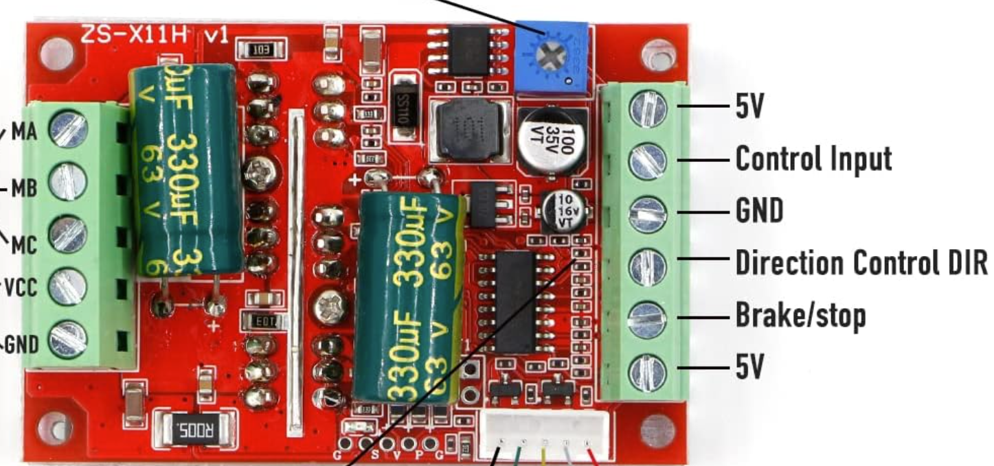
The motor controller features several input and output connections. The table below describes each pin:
| Pin Name | Type | Description |
|---|---|---|
| V+ | Power Input | Positive DC power input (6V to 60V). Connect to the positive terminal of the battery. |
| V- | Power Input | Negative DC power input. Connect to the negative terminal of the battery. |
| U, V, W | Motor Outputs | Connect to the three-phase wires of the BLDC motor. |
| GND | Signal Ground | Ground connection for control signals. |
| PWM | Control Input | PWM signal input for speed control (typically 0-5V or 0-3.3V logic levels). |
| Enable | Control Input | Enable/disable input for the motor controller. |
Usage Instructions
How to Use the Component in a Circuit
- Power Supply Connection:
- Connect the positive terminal of your DC power source (6V to 60V) to the
V+pin. - Connect the negative terminal of your DC power source to the
V-pin.
- Connect the positive terminal of your DC power source (6V to 60V) to the
- Motor Connection:
- Connect the three-phase wires of your BLDC motor to the
U,V, andWoutput terminals. Ensure the connections are secure.
- Connect the three-phase wires of your BLDC motor to the
- Control Signal Connection:
- Connect the ground of your control signal source (e.g., microcontroller) to the
GNDpin. - Connect the PWM signal output from your microcontroller to the
PWMpin for speed control. - Optionally, connect an enable signal to the
Enablepin to control the on/off state of the motor controller.
- Connect the ground of your control signal source (e.g., microcontroller) to the
- Testing:
- Power on the system and gradually increase the PWM duty cycle to control the motor speed.
- Monitor the motor's performance and ensure it operates within the specified voltage and power limits.
Important Considerations and Best Practices
- Voltage Range: Ensure the input voltage is within the 6V to 60V range to avoid damaging the controller.
- Heat Dissipation: The controller may generate heat during operation. Use a heat sink or ensure proper ventilation to prevent overheating.
- PWM Signal: Use a PWM signal with a frequency between 1kHz and 20kHz for optimal performance.
- Motor Compatibility: Verify that your motor is a 3-phase BLDC motor and does not exceed the 350W power rating.
- Polarity: Double-check all connections to avoid reverse polarity, which can damage the controller.
Example Code for Arduino UNO
Below is an example of how to control the motor speed using an Arduino UNO:
// Define the PWM pin connected to the motor controller
const int pwmPin = 9; // Pin 9 on Arduino UNO

void setup() {
  // Set the PWM pin as an output
  pinMode(pwmPin, OUTPUT);
}

void loop() {
  // Gradually increase motor speed
  for (int speed = 0; speed <= 255; speed++) {
    analogWrite(pwmPin, speed); // Write PWM signal to the motor controller
    delay(20); // Wait 20ms before increasing speed
  }

  // Gradually decrease motor speed
  for (int speed = 255; speed >= 0; speed--) {
    analogWrite(pwmPin, speed); // Write PWM signal to the motor controller
    delay(20); // Wait 20ms before decreasing speed
  }
}
Troubleshooting and FAQs
Common Issues and Solutions
Motor Does Not Start:
- Cause: Incorrect wiring or insufficient power supply.
- Solution: Double-check all connections and ensure the power supply voltage is within the specified range.
Motor Runs Erratically:
- Cause: Poor PWM signal quality or incorrect motor wiring.
- Solution: Verify the PWM signal frequency and duty cycle. Check the motor wiring for loose connections.
Controller Overheats:
- Cause: Excessive load or inadequate cooling.
- Solution: Reduce the motor load or add a heat sink to the controller.
No Response to PWM Signal:
- Cause: Incorrect PWM voltage levels or damaged controller.
- Solution: Ensure the PWM signal voltage matches the controller's input requirements (0-5V or 0-3.3V). Replace the controller if damaged.
FAQs
Q: Can this controller be used with a brushed DC motor?
A: No, this controller is specifically designed for 3-phase brushless DC motors.Q: What is the recommended PWM frequency?
A: A PWM frequency between 1kHz and 20kHz is recommended for optimal performance.Q: Does the controller support reverse motor operation?
A: No, this controller does not have a built-in reverse function. You would need an external circuit to reverse the motor direction.Q: Can I use this controller with a 24V battery?
A: Yes, the controller supports input voltages from 6V to 60V, so a 24V battery is compatible.
By following this documentation, users can effectively integrate the RioRand 350W 6-60V 3 Phase Motor Controller into their projects and troubleshoot common issues with ease.